Difference between revisions of "PowerbarQuadSwitch"
| Line 5: | Line 5: | ||
|ProjectPurpose=Infrastructure | |ProjectPurpose=Infrastructure | ||
}} | }} | ||
| − | With the use of 4x a two-way toggle switch with neutral center rest position, [[user: | + | With the use of 4x a two-way toggle switch with neutral center rest position, [[user:The_JinX]] and [[user:ultratux]] are building a simple powerbar frontend with programmable functions. We're suggesting having one switch do '''lights ON''' / '''lights OFF''', the second do '''power ON''' / '''power OFF''', the third likely do '''audio ON''' / '''audio OFF'''. Fourth switch still TBD. |
Or perhaps more logical, '''lights West ON/OFF''', '''lights East ON/OFF''', '''Power ON/OFF''', '''Audio ON/OFF'''. | Or perhaps more logical, '''lights West ON/OFF''', '''lights East ON/OFF''', '''Power ON/OFF''', '''Audio ON/OFF'''. | ||
Revision as of 00:48, 12 November 2015
| Projects | |
|---|---|

| |
| Participants | The JinX, Ultratux, Wizzup |
| Skills | |
| Status | Active |
| Niche | Electronics |
| Purpose | Infrastructure |
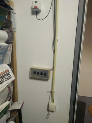
With the use of 4x a two-way toggle switch with neutral center rest position, user:The_JinX and user:ultratux are building a simple powerbar frontend with programmable functions. We're suggesting having one switch do lights ON / lights OFF, the second do power ON / power OFF, the third likely do audio ON / audio OFF. Fourth switch still TBD.
Or perhaps more logical, lights West ON/OFF, lights East ON/OFF, Power ON/OFF, Audio ON/OFF.
Currently, the box has been built, work needs to get done on making the electronics, either with an ESP and a circuit to extend that to 8 I/O pins, or <something else>. Project is currently a bit stalled due to lack of time...
A new idea hatched; instead of using an ESP and wifi etc., we are running a direct cable from the switch to the GPIO pins of the ARM board that drives the RS232 of the west space powerbar. Not only is that easier, it takes out the wifi and network as single point of failure. Thanks go out to user:Piele for initiating the discussion that led to this new idea.
The switchbox has been wired up, documentation how it is wired:
leftmost switch => green pair
next switch => orange pair
next switch => blue pair
rightmost switch => brown pair
shield (yep, it's STP for a reason): common
In all cases, pushing the switch up connects the white/colour wire to common, pushing the switch down connects the colour wire to common.
Left to do user:ultratux: run the wire up to the arm board (Mars) and put in onto a suitable header
Left to do by someone more fluent in coding: write code that evaluates the GPIO pins and tell the powerbar what function to perform.