Difference between revisions of "Wild TA-10 Innards"
(→Cutting-head base-unit) |
(→Cutting-head base-unit) |
||
| Line 33: | Line 33: | ||
This base-unit has mounting-holes for an 'cutting head option-unit' that attaches to it and is driven by signals carried over a female DB9. Among the signals available are a permanent voltage, 'light' voltage, two 'pen down' signals. | This base-unit has mounting-holes for an 'cutting head option-unit' that attaches to it and is driven by signals carried over a female DB9. Among the signals available are a permanent voltage, 'light' voltage, two 'pen down' signals. | ||
| − | |||
The base-unit has a number of switches and connectors on the top. 'Quality' is currently of unknown usefulness. 'Lighting' turns on the light-signal on the aforementioned DB9 (and is meant to provide light onto the work-surface, underneath the cutting-head option-unit). The complex-looking connector (2x7-pins) is employed to hook up the tangential cutting-attachment; most likely functioning as a stepper-motor with positional feedback for absolute-angle driving. | The base-unit has a number of switches and connectors on the top. 'Quality' is currently of unknown usefulness. 'Lighting' turns on the light-signal on the aforementioned DB9 (and is meant to provide light onto the work-surface, underneath the cutting-head option-unit). The complex-looking connector (2x7-pins) is employed to hook up the tangential cutting-attachment; most likely functioning as a stepper-motor with positional feedback for absolute-angle driving. | ||
| − | |||
| − | |||
There is a small white connector available, seemingly shielded and possibly used for some kind of sensing application. Current use unknown. | There is a small white connector available, seemingly shielded and possibly used for some kind of sensing application. Current use unknown. | ||
The PCB (PCB-H1) close to the switches is responsible for hooking them up, as well as driving/reading the signals on the DB9 connector. The place that the HF-signal is hooked up to is not quite clear. The PCB has two identifiable IC's on it; a 7404 hex-invertor and an LM339 quad voltage-comperators. The PCB carries the designator '339 170d' | The PCB (PCB-H1) close to the switches is responsible for hooking them up, as well as driving/reading the signals on the DB9 connector. The place that the HF-signal is hooked up to is not quite clear. The PCB has two identifiable IC's on it; a 7404 hex-invertor and an LM339 quad voltage-comperators. The PCB carries the designator '339 170d' | ||
| − | |||
| − | |||
A wide rainbow-ribbon cable runs to a PCB on the right side (PCB-H2); mounted next to a servo-motor that's also hooked up to this PCB. A total of 6 wires run to the servo's backside, containing a small PCB (PCB-H3) with two trim-pots on it. | A wide rainbow-ribbon cable runs to a PCB on the right side (PCB-H2); mounted next to a servo-motor that's also hooked up to this PCB. A total of 6 wires run to the servo's backside, containing a small PCB (PCB-H3) with two trim-pots on it. | ||
| − | |||
| − | |||
| − | |||
| − | |||
The PCB-H2 also has a connector for the incoming signals from the control-unit, as well as power for all of the functions of the cutting-head. This cable-tree is ensheathed in a grey protective mesh. | The PCB-H2 also has a connector for the incoming signals from the control-unit, as well as power for all of the functions of the cutting-head. This cable-tree is ensheathed in a grey protective mesh. | ||
| − | |||
| − | |||
PCB-H2 also contains a number of IC's. Sadly, photographic documentation has too little detail to make out part-numbers. | PCB-H2 also contains a number of IC's. Sadly, photographic documentation has too little detail to make out part-numbers. | ||
| + | <gallery> | ||
| + | File:Wild TA10-head1.jpg|DB 9 connector for cutting head option unit | ||
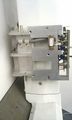
| + | File:Wild TA10-head2.jpg|Top of cutting head, overview of PCB and cables | ||
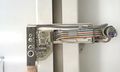
| + | File:Wild TA10-head3.jpg|Top of cutting head, detail of switches and PCB | ||
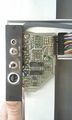
| + | File:Wild TA10-head4.jpg|Detail of back of servo-motor | ||
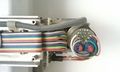
| + | File:Wild TA10-head5.jpg|Detail of PCB-H3, showing rainbow-ribbon and servo-motor connections | ||
| + | </gallery> | ||
==== Cutting-head option-unit ==== | ==== Cutting-head option-unit ==== | ||
Revision as of 16:25, 29 October 2013
Wild TA-10; Innards.
Overview of units
To simplify documentation, it's often handy to separate things in terms of functionality as much as possible and document these accordingly. In an effort to make a handy/useful overview; an effort to identify seperate functions is proposed here.
Units/functions
Mechanical
Base unit
Table unit
Arm unit
Cutting Head
Piston/hinge unit
Nobody's really taken this apart yet, and we've got good reason to assume that this is a non-trivial thing to even attempt. More to the point, we've received warnings about leaving the spring-assembly intact as re-assembly could be problematic.
It should be noted that the Piston does not seem to have any wires routed through it and is a purely mechanical construction.
Electronics
Power Supply
Control Unit
CPU board
I/O board
Servo amplifiers
Table unit
Wire-routing
Lighting system
Cutting-head unit
Cutting-head base-unit
The Y-arm has an actuator that moves along it in vertical direction. We shall refer to this as the 'base' unit.
This base-unit has mounting-holes for an 'cutting head option-unit' that attaches to it and is driven by signals carried over a female DB9. Among the signals available are a permanent voltage, 'light' voltage, two 'pen down' signals.
The base-unit has a number of switches and connectors on the top. 'Quality' is currently of unknown usefulness. 'Lighting' turns on the light-signal on the aforementioned DB9 (and is meant to provide light onto the work-surface, underneath the cutting-head option-unit). The complex-looking connector (2x7-pins) is employed to hook up the tangential cutting-attachment; most likely functioning as a stepper-motor with positional feedback for absolute-angle driving.
There is a small white connector available, seemingly shielded and possibly used for some kind of sensing application. Current use unknown.
The PCB (PCB-H1) close to the switches is responsible for hooking them up, as well as driving/reading the signals on the DB9 connector. The place that the HF-signal is hooked up to is not quite clear. The PCB has two identifiable IC's on it; a 7404 hex-invertor and an LM339 quad voltage-comperators. The PCB carries the designator '339 170d'
A wide rainbow-ribbon cable runs to a PCB on the right side (PCB-H2); mounted next to a servo-motor that's also hooked up to this PCB. A total of 6 wires run to the servo's backside, containing a small PCB (PCB-H3) with two trim-pots on it.
The PCB-H2 also has a connector for the incoming signals from the control-unit, as well as power for all of the functions of the cutting-head. This cable-tree is ensheathed in a grey protective mesh.
PCB-H2 also contains a number of IC's. Sadly, photographic documentation has too little detail to make out part-numbers.
DB 9 connector for cutting head option unit
Top of cutting head, overview of PCB and cables
Top of cutting head, detail of switches and PCB
Detail of back of servo-motor
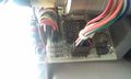
Detail of PCB-H3, showing rainbow-ribbon and servo-motor connections


