User:Chotee/constantCurrentSink
Jump to navigation
Jump to search
Constant Current Sink
Goal: Will sink a constant current independent of the input voltage.
Range: 1mA to 5000mA. Max Vin 30V.
Ref 1 Build Notes
Update 2015 07 15
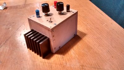
Made the box mostly out of 10mm plywood. It's a quick job. Adding the decal is needed.
Update 2015 06 20
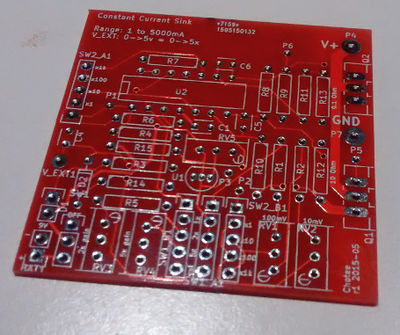
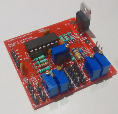
The bare PCB and populated PCB.
Adjustment
- RV5 (reference voltage adjust) to 5V. Test point at P3.
- Set SW_A1 to non-EXT value
- RV1 (100mV voltage) to 100mV. Set SW2_B1 to bottom value, Set SW1_B1 to 1x gain (top pin). Use P1 as test point.
- RV2 (10mV voltage) to 10mV. Set SW2_B1 next to bottom, Set SW1_B1 to 1x gain. Use P1 as test point.
- RV3 (2x gain) to 100mV/10mV. Set SW1_B1 to 2x gain. Adjust until 200mV/20mV on P1
Errata
- R5 @ 1k8: wrong value. Cannot get 2x gain with 1k8+5k pot. Change to 6k8+5k pot to get 2x gain.
- R15 @ 10K: Doesn't give enough current to the LM336Z5.0. Switch to a lower resistance, 3k9 works for 9v input but. If 9v battery is used, voltage will droop till 7v during battery life. R15=1k5 will give stable reference 5V with a Vbat of 9V5 to 7V. Quiescent current does go up, but usable battery life will still be longer.
Possible improvements for next ref
- Reduce reference voltage to 2V5 or 1V25. 5V is not needed. 5V external input can be divided to get reference voltage.
- Investigate the use of a Instrumentation Opamp for voltage voltage comparisons and better controlled gain. INA126's are on hand.
- Use a relay (or some such) to switch between 0R1 and 10R resistor shunts, reducing needed MOSFETs and voltage comparison to one.
- Use 2 or 3 AA batteries instead of 9V and use boost converter to create needed higher voltages.
- Improve the enclosure. Using 3mm wood or sheet plastic. The knobs do not fit very well, but do the job.
Links
- LM336z5.0: http://www.ti.com/lit/ds/symlink/lm136-5.0.pdf
- 9v battery characteristics: http://ww2.duracell.com/media/en-US/pdf/gtcl/Product_Data_Sheet/NA_DATASHEETS/MN1604_6LR61_US_CT.pdf
- Instrumentation opamp: http://www.ti.com/product/INA126/description


