Cerberups
| Projects | |
|---|---|
| Participants | Ultratux |
| Skills | Woodworking, precision assembly, electronics, fine mechanic |
| Status | Active |
| Niche | Mechanics |
| Purpose | World domination |
Introduction
Cerberups, a Delta-type 3D printer. It is a slight modification to a US design, the Cerberus, see https://github.com/grabercars/Cerberus. My modifications were mainly necessary to adapt from imperial to metric extrusions, but also because other choices were made in type of materials (ie. wood instead of PLA). The Cerberus itself is based on the Rostock, of course: the first delta 3D printer.
First steps
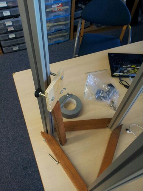
First uneasy steps. This was rather hard; the used wood is a very hard and tough kind. And it's only when you need a 30 degree angle, you find that none of our tools have any setting for it, or they are so coarse/imprecise as to be completely useless... Examples: I wanted to buy a mitre box with a 30 & 60 degree cut-- unobtainable. And our mitre saw has a 60 degree angle, but can't manage 30 degrees... Oh well. Lots of improvisation. Lots of extensive postwork on the very resistant wood...
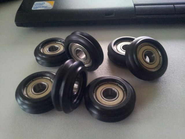
Coating specially crafted by Steve Graber (the designer of the Cerberus) on his state-of-the-art CNC lathe. These are at the heart of the vertical movement system used in the Cerberus. Get these babies wrong, and gone is precision & accuracy, and gone is silent movement.
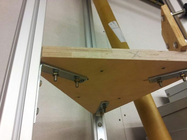
Decided to go with wood instead of printing in PLA, for a host of reasons; Our other printer is in a state of constant testing, rebuilding, breaking and fixing and not deemed production ready yet. Secondly these printed parts are so massive I'd need to babysit our printer for 48 hours or more, even if it doesn't fail halfway. And third, adaptation from imperial to metric proves hard to do, since my extrusions also have a slightly different profile, so it needs a lot more work than just scaling up by 105%, sadly.
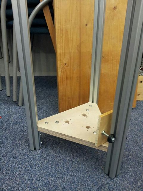
After retrieving my router and making the mounts for the three steppers, I could now bolt it in place in a more permanent fashion. Not too happy with the extrusions not being 100,0% parallel yet, but we're getting there. Robustness though, is already quite good now.
I must await delivery of the stepper motors and must find a way to get the three carriages printed. In the meantime I will find some means to re-make the bottom dual idler mounts and the top idler + tensioner in something other than PLA. So, get creative, Maarten!
Milestone one
My stepper motors have arrived. I did work on the bottom idler, made from thick aluminum and drilled in interesting and difficult ways with the drill press. But I really hit a brick wall trying to design the top idler/tensioner. First I attempted something that slid into the gap in the extrusion completely, but I got stuck trying to join two thin aluminum plates to a center piece, without any part or bolt protruding. As it turned out, glueing proved infeasible too; epoxy reportedly can glue metals fine, with the exception of... aluminum. :-(
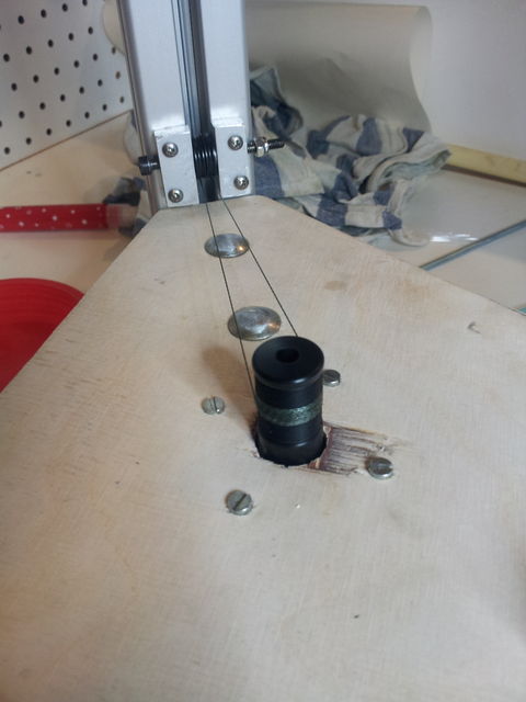
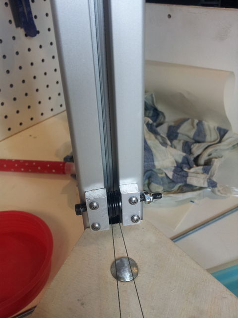
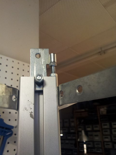
Then I thought something up: I could use one of the corner round holes to put a threaded rod there, and use a nut to tension it. Then from there the idea developed further and further. Two trips to Gamma and I had made it from M5 threaded rod, a hinge and some other parts. \o/ Next up was of course threading the whole assembly to make a working proof-of-concept with a single column. This proved extremely hard; it is astonishingly hard to try to attach the thin wire to the nail attached to the carriage, and it is especially hard to get the thread out of the gap next to the idler once it has wedged itself completely in there. :-( But the result is there now. Works vfine it seems, but I'll have to wait until the stepper can be electronically driven. See these four pics.
