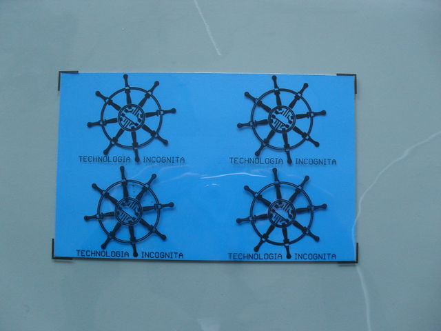
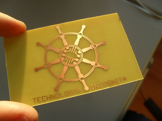
PCB Techinc Logo
| Projects | |
|---|---|
| |
| Participants | Brainsmoke |
| Skills | Etching, Soldering |
| Status | Finished |
| Niche | Electronics |
| Purpose | World domination |
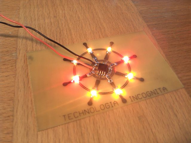
Since our logo is a working PCB design, we thought it was time we have a working circuit.
Contents
Techinc Logo PCB mkII
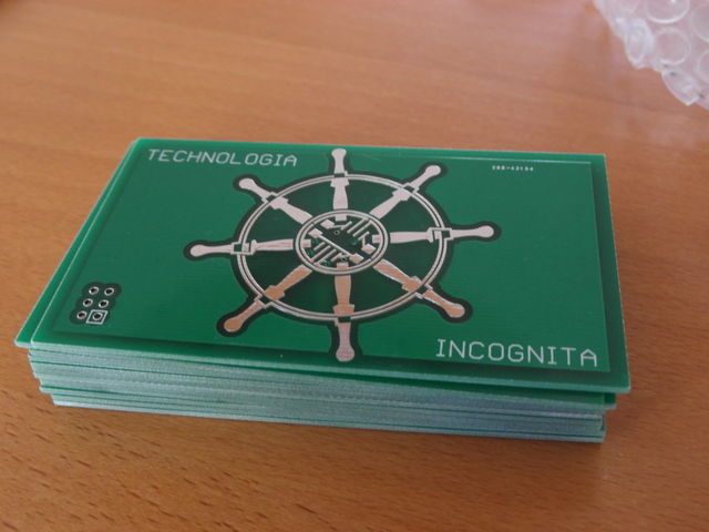
techinc_badge ordered from iTead studio
Build Instructions
| Element | Quantity |
| Attiny85 | 1 |
| Red LED SMD 1206 | 4 |
| Yellow LED SMD 1206 | 4 |
| Resistor 10K Ohm SMD 1206 | 1 |
| Resistor 18 Ohm or 22 Ohm SMD 1206 | 4 |
| CR2032 Battery | 1 |
| CR2032 Battery Clip | 1 |
| 2x3 .1" Pin Header for ISP (optional) | 1 |
| Safety pin (optional) | 1 |
Pre-tin all the pads you will be using.
When soldering the LEDs to the board you must start with the upper most one.
the cathode (negative) must be on the outer most pad
starting clockwise, we will add all the other LEDs. The next LED must have its anode (positive) pad pointing outward.
Continue to alternate the polarity of the LEDs until you have soldered all 8.
You can figure out the polarity of your SMD LED here http://www.niktronixonline.com/Articles.asp?ID=140 . Another easy way of checking is to use the diode tester on a multimeter.
add the 18 or 22 ohm resistors in the positions shown below
add the final resistor
solder on the chip with the notch pointing to the right
Finally solder the battery clip on the backside
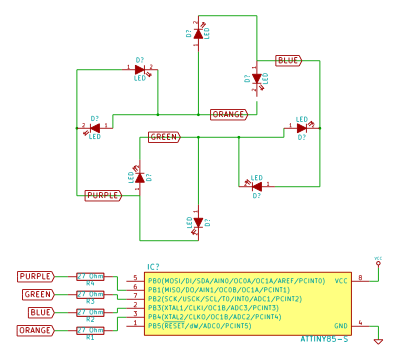
Schematic
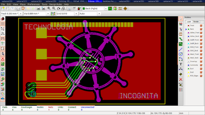
Circuit board
Code for AVR
File:Techinc badge code.tar.gz
https://github.com/techinc/techinc_logo_avr
