Difference between revisions of "Cerberups"
m |
m (add category) |
||
| (97 intermediate revisions by one other user not shown) | |||
| Line 1: | Line 1: | ||
{{Project | {{Project | ||
| − | |ProjectSkills= | + | |ProjectSkills=Metal- and woodworking, precision tooling, assembling, electronics, fine mechanics, creative thinking |
| − | |ProjectStatus= | + | |ProjectStatus=Finished |
|ProjectNiche=Mechanics | |ProjectNiche=Mechanics | ||
|ProjectPurpose=World domination | |ProjectPurpose=World domination | ||
}} | }} | ||
| − | + | =Introduction= | |
| − | |||
| − | Cerberups, a Delta-type 3D printer. It is a slight modification to a US design, the Cerberus | + | Cerberups, a Delta-type 3D printer. It is a <s>slight</s> radical modification to a US design, the Cerberus by Steve Graber of Grabercars (see https://github.com/grabercars/Cerberus). My modifications were mainly necessary to adapt from imperial to metric extrusions, but also because other choices were made in type of materials (ie. wood instead of PLA). The Cerberus itself is based on the Rostock, of course: the first delta 3D printer. <br> |
| − | <br> | + | My chosen name Cerberu'''p'''s is a wordplay because it so differs from the original and I don't want to put people on the wrong foot by implying that mine is anything like the original (except concept and key parts). Rups is Dutch for ''caterpillar''. |
| − | + | =First steps= | |
| − | First | ||
| − | [[File:coated_bearings.jpg| | + | [[File:coated_bearings.jpg|560px]]<br> |
| − | + | 608 bearings with coat/sleeve (Delrin I believe) specially manufactured by Steve Graber on a state-of-the-art CNC lathe. These are at the heart of the vertical movement system used in the Cerberus. Get these babies wrong, and gone is precision & accuracy, and gone is silent movement. I ordered the rollers, idler wheels and filament drive reels at Steve Grabers webshop. Couldn't have done this entire project without those. <br><br> | |
| − | [[File:second_day.jpg| | + | [[File:second_day.jpg|560px]]<br> |
Decided to go with wood instead of printing in PLA, for a host of reasons; Our other printer is in a state of constant testing, rebuilding, breaking and fixing and not deemed production ready yet. Secondly these printed parts are so massive I'd need to babysit our printer for 48 hours or more, even '''if''' it doesn't fail halfway. And third, adaptation from imperial to metric proves hard to do, since my extrusions also have a slightly different profile, so it needs a lot more work than just scaling up by 105%, sadly.<br><br> | Decided to go with wood instead of printing in PLA, for a host of reasons; Our other printer is in a state of constant testing, rebuilding, breaking and fixing and not deemed production ready yet. Secondly these printed parts are so massive I'd need to babysit our printer for 48 hours or more, even '''if''' it doesn't fail halfway. And third, adaptation from imperial to metric proves hard to do, since my extrusions also have a slightly different profile, so it needs a lot more work than just scaling up by 105%, sadly.<br><br> | ||
| − | [[File:third_day.jpg| | + | [[File:20130513 213312.jpg|400px]]<br> |
| + | Routed holes for stepper motors <br><br> | ||
| + | |||
| + | [[File:third_day.jpg|400px]]<br> | ||
After retrieving my router and making the mounts for the three steppers, I could now bolt it in place in a more permanent fashion. Not too happy with the extrusions not being 100,0% parallel yet, but we're getting there. Robustness though, is already quite good now.<br> | After retrieving my router and making the mounts for the three steppers, I could now bolt it in place in a more permanent fashion. Not too happy with the extrusions not being 100,0% parallel yet, but we're getting there. Robustness though, is already quite good now.<br> | ||
<br> | <br> | ||
I must await delivery of the stepper motors and must find a way to get the three carriages printed. In the meantime I will find some means to re-make the bottom dual idler mounts and the top idler + tensioner in something other than PLA. So, get creative, Maarten!<br> | I must await delivery of the stepper motors and must find a way to get the three carriages printed. In the meantime I will find some means to re-make the bottom dual idler mounts and the top idler + tensioner in something other than PLA. So, get creative, Maarten!<br> | ||
| + | |||
| + | =Milestone one= | ||
| + | |||
| + | My stepper motors have arrived. I mounted them, I filed a notch into the axle to help the set screw grip the axle. All that wasn't very interesting nor hard, so I've included no pics of that. | ||
| + | |||
| + | Then I did work on the bottom idlers block, made from thick aluminum and drilled in interesting and difficult ways with the drill press. Bit of trivia: A thick enough piece of aluminum was hard to find, or even near-impossible to find. I wandered around in my local shop until I got lucky in the coat hangers / shelf support aisle: I found a support made of good, thick 8mm aluminum. I even used other parts a bit later on, quite unexpected and ''quite'' welcome.<br> | ||
| + | |||
| + | [[File:20130514_204333.jpg|560px]]<br> | ||
| + | Drilling on the edge...<br><br> | ||
| + | |||
| + | [[File:20130514_232455.jpg|560px]]<br> | ||
| + | Finished bottom idler support block. I had to specially buy a 4.1 mm drill to make the ID of the idlers a tad larger, because a 4.0mm ID idler does not fit on a 4.0 mm OD rod. Well, it fits, but then you'd need pliers to turn it...<br><br> | ||
| + | |||
| + | But I really hit a brick wall trying to design the top idler/tensioner. First I attempted something that slid into the gap in the extrusion completely, but I got stuck trying to join two thin aluminum plates to a center piece, without any part or bolt protruding. As it turned out, gluing proved infeasible too; epoxy reportedly can glue metals fine, with the exception of... aluminum. :-( | ||
| + | |||
| + | Then I thought something up: I could use one of the corner round holes to put a threaded rod there, and use a nut to raise it to provide the tensioning mechanism. Then from there the idea developed further and further. Two trips later and I had made it from M5 threaded rod, a partly sawed hinge and some other parts. \o/<br> | ||
| + | It did need some hard, precise and error-prone machining though. It may be interesting to read: As I have very little room in the extrusion, I deployed coach bolts, whose heads I made really thin and flat with a grinder. That was nice but it has obvious drawbacks too of course; I needed to file round the square inset of the shaft too, 'cause that is where my idler would be. And then, finding a ring with ID that fits over that rounded shaft and OD to fit inside the 8mm ID idler... that was a bitch. I could not deploy plastic bushes like you find in electronics, since the plastic against plastic really didn't feel it would run smoothly. I sadly had no immediate source of small pipes/tubes at the time I wanted to test/finish my design. After again a walk through my department store I came to the realization that the aluminum support I had bought as my source of thick aluminum was also equipped with an aluminum rod which measured... 7,7 mm OD. Wow... talk about being lucky! A bit of work with drill, saw, file and caliper and it was done.<br><br> | ||
| + | |||
| + | Next up was of course threading the whole assembly to make a working proof-of-concept with a single column. Threading the drive-filament proved extremely hard; it is astonishingly hard to try to attach the thin wire in the inside of the column to the nail attached to the carriage, and it is especially hard to get the thread out of a gap next to an idler once it has wedged and pulled itself completely in there. :-( | ||
| + | |||
| + | But the result is there now. It works fine it seems, but I'll have to wait until the stepper can be electronically driven to verify. See these five pics. | ||
| + | <br> | ||
| + | |||
| + | [[File:20130517_211239.jpg|400px]]<br> | ||
| + | Stepper motor with 9 or 10 windings on axle (axle courtesy of Steve Graber of Grabercars)<br><br> | ||
| + | |||
| + | [[File:20130517_211242.jpg|400px]]<br> | ||
| + | Closeup of bottom idlers <br><br> | ||
| + | |||
| + | [[File:20130518 212420.jpg|400px]]<br> | ||
| + | The tensioner with idler wheel <br><br> | ||
| + | |||
| + | [[File:20130517_211250.jpg|400px]]<br> | ||
| + | The tensioner with idler wheel inside extrusion <br><br> | ||
| + | |||
| + | [[File:20130517_212752.jpg|400px]]<br> | ||
| + | The tensioner with idler wheel inside extrusion, view from top <br><br> | ||
| + | |||
| + | I asked BuZz of http://nurdspace.nl/Main_Page to print the three carriages and the platform in PLA. They came out excellent. They look a bit bashed now on the pictures but that is because of me filing them, not because they looked this way when delivered. Many thanks, BuZz ! Your printer creates amazing quality stuff! <br><br> | ||
| + | |||
| + | [[File:20130521 180754.jpg|560px]]<br> | ||
| + | The printed carriages needed a fair bit of filing down due to differences in extrusion profile and the 105% scaling, but still trivial to do. I don't fear it will weaken the construction because the forces work in other directions than which would be risky. <br> | ||
| + | Um, yeah. In case I hadn't mentioned: the original Cerberus parts were made for 1.5" extrusions. I deploy 40mm extrusions. 1.5 inch -> 40mm has a ratio of 1.0498687664 or 1.05x. Hence me printing them at 105% scale.<br><br> | ||
| + | |||
| + | [[File:20130521 213328.jpg|400px]]<br> | ||
| + | The 65lb fishing gear glands I first got were way too big to fit inside the extrusion cavity so I got smaller ones. I highly doubt the tension would ever really reach such immense levels under normal operating circumstances anyway. Oh and, making the knots is a '''major pain''' but with patience and perseverance... even my big clumsy male hands could eventually pull it off.<br><br> | ||
| + | |||
| + | [[File:20130521 000408.jpg|400px]]<br> | ||
| + | It seems to fit perfectly. A tad on the strained side but I see no ill effect from that. It very efficiently takes away all chances of play, so very very accurate <br><br> | ||
| + | |||
| + | =Milestone two= | ||
| + | |||
| + | [[File:20130521 215225.jpg|400px]]<br> | ||
| + | Milestone 2: All three carriages / axis mounted, threaded, moving smoothly, good to go!<br><br> | ||
| + | |||
| + | [[File:20130525 224439.jpg|400px]]<br> | ||
| + | Just normal dependable mechanical endstops, none of this optical endstop blah blah. Mounted on a piece of thread to give the tensioner nut room to move all the way down. Later, I need to engineer it so that the latch of the microswitch doesn't get caught by the slotted screw head when the slot is exactly at a right angle to it. Or simply deploying other screws...<br><br> | ||
| + | |||
| + | [[File:20130530 000306.jpg|560px]]<br> | ||
| + | Top bracket also made out of wood. Much better looking than tiewraps! <br><br> | ||
| + | |||
| + | [[File:20130530 020113.jpg|400px]]<br> | ||
| + | Four of the six arms done and glued. It is very hard to ascertain equal length, this is mainly because there isn't really any endstop anymore on the plastic joints; any that might have been there have been filed down while making it fit the ID of the aluminum tube. I'll do my best, and eventually redo ones that are bad. The two arms aren't exactly parallel, I am therefore thinking of redoing printhead platform joint connections with longer M2 threaded rod + 3mm aluminum tube... And I was about to find out just '''HOW MUCH''' those rods really needed to be exactly parallel too...! <br><br> | ||
| + | |||
| + | [[File:20130530 020143.jpg|400px]]<br> | ||
| + | Closeup detail of top joints on carriage. The two-component adhesive I've used is interesting; it literally gives you maybe 120-150 seconds to deploy, after that it has become too hard already to use. Challenging stuff but quite neat and useful 'cause I ''really really'' hate to wait for glue to dry!<br><br> | ||
| + | |||
| + | After all three axis were glued and I started moving the platform around I got quite a '''scare''' though. ''The platform didn't stay level!'' '''AT ALL!''' <br><br> | ||
| + | |||
| + | [[File:20130530 040904.jpg|400px]]<br> | ||
| + | At first I thought that must have been because I reckoned the length of the rods was non-critical provided all six were identical. '''''What stupidity of me !''''' Now I would have to do them all over ''':-(''' <br> | ||
| + | Luckily, a forum pointed me to the real reason; it wasn't the length that was wrong, it was that I neglected to make sure the rods were perfectly parallel; At the top end their distance was wider by quite a margin than at the bottom end. And that -luckily- was far simpler to rectify.<br><br> | ||
| + | |||
| + | [[File:horizontalagain.jpg|400px]]<br> | ||
| + | See here the result after rectifying that error. Now the rods are parallel, and the platform stays level throughout its field of movement now!<br><br> | ||
| + | |||
| + | =Filament, Hotend, etc= | ||
| + | |||
| + | Today I did expect to receive my new minitronics controller board. But the PostNL mail delivery decided differently :-( Therefore, I spent today making other stuff, spending "too much" time making them too nice and neat, 'cause you need to make time pass... So I made a very nice filament spool holder with actual 608 bearings. And a mounting clamp for the J-head hotend.<br><br> | ||
| + | |||
| + | [[File:20130531_234443_resized.jpg|400px]]<br> | ||
| + | Made this with parts we had in stock. Well except 8mm rings, those I had to scavenge for everywhere: we need to stock up on those. I grinded one nut slightly askew, so the holder is a bit tilted so as to prevent the spool falling off. The extruder (Airtripper direct drive for bowden) will be placed just above this.<br><br> | ||
| + | |||
| + | [[File:20130531_234517_resized.jpg|400px]]<br> | ||
| + | With 1 Kg reel of 1.75 mm filament. The plastic pipe it sits on I had to grind down a very small bit to make it fit into the spool. That was not nice: it is hard to turn down a pipe, even if only by 0.5 mm<br><br> | ||
| + | |||
| + | [[File:20130531_234528_resized.jpg|400px]]<br> | ||
| + | I found two pieces of aluminum that together were '''exactly''' the thickness of the slot in the PEEK hotend. Decided to make two U-forms that enclose it completely by placing one reversed. Did this extra-neat with lots of patience, pillar drill, drill fluid, very careful filing, sanding, caliper, etc. It fits like a latex glove around a hand. I use two M2 screws to hold the two halves together but they fit so tight, I'm confident the screws are unnecessary.<br><br> | ||
| + | |||
| + | [[File:20130531_235555_resized.jpg|400px]]<br> | ||
| + | With mounted hotend bracket, J-head 0.5mm-for-1.75mm hotend, PLA cooling fan<br><br> | ||
| + | |||
| + | [[File:20130602 215322.jpg|400px]]<br> | ||
| + | With painstaking precision I rolled I believe some 20-30 layers of aluminum foil around the heater resistor to make it fit very snugly in the channel. I like the result very much, but what a tedious and error-prone job that was...<br><br> | ||
| + | |||
| + | [[File:20130602 215358.jpg|400px]]<br> | ||
| + | Before you laugh at me and tell me I'm stupid-- no, these aren't plastics around the wires, they're taken from a high temperature proof PTFE wire, you can still see the disassembled pieces of the wire in the immediate background. Will have to run endurance tests still, but first test was passed without a glitch: stuff doesn't start melting, even when heated with soldering iron for 20 seconds.<br><br> | ||
| + | |||
| + | [[File:20130603 001828.jpg|400px]]<br> | ||
| + | Okay so, some background info first. I use a bowden and a J-Head. Normally the J-Head comes with a hollow set screw to put enough pressure on the PTFE inside to prevent leaking, yet not prevent the PLA from moving by pinching too hard. But in my case, it is highly illogical to end the bowden just above the hotend, cross an air gap, and enter an identical piece of PTFE again inside the J-Head. <br><br> | ||
| + | |||
| + | [[File:20130603 001836.jpg|400px]]<br> | ||
| + | Therefore I had to improvise a bit. I need/want to deploy one continuous bowden PTFE from extruder motor, all the way inside to the hot nozzle. I needed something directly on top of the J-Head to be able to finely adjust the force by which the PTFE is pushed in. Enter a hinge and some drilling and soldering. The screw head is flattened on one side, together with the soldered-on ridge it prevents the screw from turning, yet still enables it to change orientation.<br><br> | ||
| + | |||
| + | [[File:20130603 003349.jpg|400px]]<br> | ||
| + | The assembly mounted on the platform. I used two tight-fitting nuts to try and grip the PTFE. We'll have to see how well that stands up to the pressure... Afterwards one needs to drill out the PTFE again with a 2.0 mm drill bit, because the nuts compress it to the point of not being able to pass the filament through the PTFE anymore.<br><br> | ||
| + | |||
| + | [[File:20130603 003430.jpg|400px]]<br> | ||
| + | I plan to change the M2.5 nut you see (the adjuster for the pressure) to a wingnut if I'm able to source that. I also still need to devise some way preventing that nut from slowly loosening itself over time with the constant vibrations and movement.<br><br> | ||
| + | |||
| + | [[File:20130603 015821.jpg|400px]]<br> | ||
| + | The mounting of the thermistor is, once you start thinking about it, a real challenge. The wires are not insulated, so they will gladly short against each other or against the metal hotend. I possess very thin lacquer-insulated wire but nothing tells me that would withstand 200 degrees Celcius. But it's worse still; one cannot expect a solder joint to hold when the temperature is steady around 200 degrees. And even if one could, the final stretch of wire will still be uninsulated, precisely at the critical spot: inside the tiny 2mm hole. So umm... Kapton tape? meh. Ugly, error prone, flaky. Then I thought of simply just insulating only one of its wires. The hotend isn't electrically connected to anything, so shorting the one wire to it has no effect. And insulating just one wire is very doable; I've used the same PTFE sheath from the dissected wire I used above, only now I made a tiny 1mm incision in the top, so the thermistor can be "half pulled in", making the insulation almost foolproof and greatly simplifying the insertion in its hotend spot too. <br><br> | ||
| + | |||
| + | =Calibration etc= | ||
| + | |||
| + | [[File:20130604 015030.jpg|560px]]<br> | ||
| + | So in a bold and unprecedented move while looking to buy a round glass plate or mirror, I found this piece of slate in a shop. It looks fairly flat, was ridiculously cheap, and I suspect its heat conducting properties are much better than glass. I will try to use this as platform, either with or without a heat source underneath, and either with or without tape to help the PLA adhere. I stand to lose nothing; I can still purchase glass and throw this 3,50 euro investment in the trash if it is really unsuited.<br> | ||
| + | |||
| + | Heh. Well, I used this to try and calibrate, which is a tough job; Sometimes the printer acts erratic, like not reacting to home (G28) commands or moving in random faulty directions, and the math doesn't add up if you recalibrate Z height, strangely enough (if you touch the platform with Z=58 and you decrease MANUAL_Z_HOME_POS with 58, Z=0 *does* *not* touch the platform... Go figure.<br> | ||
| + | I did succeed in at least getting all the numbers nicely close to correct; it now hovers over the platform if I select Z=2, at equal distances in front of all three towers, and it also looks to have the same clearance in the middle. That is great progress compared to yesterday. But a lot of that is still visual, no measurements to back that up. And in hindsight that is a good thing, because the slate looks flat when you look at it with your eye, but when you hold a ruler over it you see very clearly it's not. It has at least 1mm-2mm difference in the middle. So it is a good thing I didn't spend hours precisely tweaking using that as my reference. So further work needs to be done, and a better work surface needs to be acquired. <br><br> | ||
| + | |||
| + | You can see a short clip of it moving about over here: https://www.youtube.com/watch?v=B0ajfRH5b6k&feature=youtu.be <br><br> | ||
| + | |||
| + | Been looking everywhere for a nice round 30cm glass plate, like in second hand stores, on our local ebay variant, in shops. I also bought some items, like a cheap wall clock which ''did'' prove to have a glass faceplate despite that the clerk was adamant it was plastic, and a mirror. But, the glass proved way too thin and had an untreated edge so it was an accident waiting to happen, and the mirror was simply too small. Slowly getting desperate, I found a 30 cm glass cookingware turntable in a Blokker shop. This was in fact, more perfect as I could've imagined; hardened glass, temperature proof, totally smooth edges, extremely flat, virtually unbreakable, and exact the right size. I '''''just''''' had to remove the glued-on center axle/pivot. That proved hard, but possible with extreme force and a lot of solvent to try and weaken the bond...<br> | ||
| + | [[File:20130614 151950.jpg|400px]]<br><br> | ||
| + | |||
| + | =New Electronics!= | ||
| + | |||
| + | Received Minitronics board from Reprapworld. As I believe in passive cooling I decided to put some sort of heatsink on the stepper drivers. I settled for making one strip that sits on top of all 4 chips, glued on with special heat-conductive glue. The glue took '''''very''''' long to cure, so that made things "interesting". But anyway, this is the heatsink I created by carefully sawing off a slice of an old PC CPU cooler. And pic 2, glued onto the PCB.<br><br> | ||
| + | [[File:20130601 153342.jpg|400px]]<br> | ||
| + | [[File:20130821 135436.jpg|400px]]<br><br> | ||
| + | |||
| + | The software part -now that I write this, weeks later- is now a bit vague/forgotten. I did make some notes of things that took a while to figure out. One of those is a mention that pins.h needs to be merged, not overwritten. Then there was also a matter of the endstops not properly being defined in there: a delta uses "MAX_ENDSTOP", not "MIN_ENDSTOP". It was either not there, or no actual Arduino pins were properly assigned to these definitions. Until that is fixed, all tinkering with endstop settings in configuration.h is '''meaningless''' because they will simply not work and the motor will not stop, trying to push through the endstop, which makes you dash for the power button! | ||
| + | |||
| + | Also a tip: In Pronterface, the translations between XYZ and delta mode have ''already been done'' (in firmware). So if you give movement instructions to the X axis motor, you don't just drive the one "X" motor, you would drive all 3(!) motors in order to move the head in the X direction. '''BUT''' when you have just wired everything up, some motors will be reversed, adding to the general confusion and you'll not know how to interpret what happens. So here is my tip: '''forget''' about X and Y movements! If you click on the Z down or up button, '''all three''' motors should move equal amounts, and '''''all in the same direction!'''''. Fix that first by reversing motors (either in software or in hardware) and after that X and Y movement buttons will all of a sudden make much more sense. It took me a while to figure this out, it is completely obvious when you know, but if it is your first time stuff can really be rather opaque to the observer... | ||
| + | |||
| + | Further random tips or observations: slic3r has by default a command to home '''only''' the X axis after finishing a print. And by some misunderstood magic, they now mean not some X coordinate somewhere, but simply move the X motor until the X endstop gets hit (so here, this is untranslated, raw XYZ-speak to a delta setup). This is pure evil on a delta, since it will cause the print platform to hit into one of the towers, and keep on headbutting into it until something breaks, or power gets cut off. Remove that command or replace it by a "G28" (home all axis). Do it '''now'''. Don't hesitate! You've been warned.<br> | ||
| + | |||
| + | =Heating up, extruding= | ||
| + | |||
| + | After the calibration I couldn't stop myself from wanting to test the hotend+bowden+heater resistor I made. So I put in the thermistor with the use of some kapton, chose the right value in Configuration.h and very cautiously typed in "M104 S50" and lo and behold, it got warm! After some internal debate about not being able to pull the PLA out cleanly anymore I went and pushed it to 190 degrees and pushed in a length of filament through the bowden tube. And I pressed on. And yep, out it came, a nice thin blue strand of PLA. Whoa. Science, bitches! \o/<br> | ||
| + | |||
| + | Now I '''''really''''' want my extruder...<br><br> | ||
| + | |||
| + | =Movement issues= | ||
| + | |||
| + | Aside all this seemingly very good news, there is also bad news. In my enthusiasm I did press for some high speeds and the machine '''REALLY''' doesn't cope well with that. It resonates, it routinely shows very weird glitches as if the driving filament is rubber instead of spectra (jumping and hesitating and having severe hiccups and bumps, but still apparently not skipping because the attained end point is still where it is supposed to be (weird). I am unsure if my speed expectations are quite simply too high, or that I need to tweak speed settings so as to try and avoid resonance frequencies, or that the filament is too tight or too loose, the stepper current is too high or too low, some problems with bearings, whatever. Although we did experiment with the tension which didn't show improvement. | ||
| + | Maybe it is more of a software thing and acceleration settings must be tweaked and more intelligent movement commands instead of my crude GCode that tells it to very abruptly stop, change directions, etc. Who knows. But at the moment, it is no speed monster yet...<br><br> | ||
| + | |||
| + | |||
| + | =Success at last!?= | ||
| + | |||
| + | Yay! Tonight marks the first successful print, not counting the 25mm calibration pyramids.<br> | ||
| + | [[File:20130620 041801 resized.jpg|400px]]<br><br> | ||
| + | |||
| + | |||
| + | =Meltdown!!= | ||
| + | |||
| + | Yep, the inevitable happened; My naive belief that the thermistor would stay in its snug hole inside the hotend despite not being glued in there, eventually became a myth. A distinct penetrating smell of molten plastics together with some other worrying effects and now it looks like the hotend ejected itself a bit from the PEEK holder. Ohnoes, it is broken and I have to wait for spare parts to arrive in the mail... Bummer!<br> | ||
| + | <br> | ||
| + | |||
| + | But I sorted it out, got a fresh PEEK holder, spent an afternoon taking the whole assembly apart and back together again. I now have the thermistor mounted much better; I could get hold of some awesome micro PTFE insulation tubes, and I deployed some sort of high temp heatsink kit to glue it. Kit is supposed to be fine up to 200 degrees but I'm printing with PLA so I'm not very worried there. | ||
| + | |||
| + | =Cheered too soon; more debugging and problemsolving= | ||
| + | |||
| + | As can be seen from the first print there was a '''lot''' of stringing, but that's only the very beginning of the sorrows... | ||
| + | |||
| + | I printed some things fairly successfully, like a statue. | ||
| + | |||
| + | [[File:20130626 224358 resized 1.jpg|560px]]<br> | ||
| + | |||
| + | Others were disastrous. The ever-present common factor seemed to be extruder problems. '''Severe''' extruder problems. Perimeters went reasonably okay, infill was a disaster. So I adjusted speeds, but it never got to a good point. I had endless trouble. I've had the bowden break loose on two occasions, slippage and skippage, and the motor not turning due to not enough electric energy, etc. I upped current, even to the max the stepper driver could manage, but that didn't solve it. It did necessitate me force-cooling the stepper motor though. | ||
| + | I changed the connection of the bowden (now pressfit!) and had to adapt that several times because now the clearings where the filament could (and '''would''') get folded up/jammed were too long. But in the end, I returned to the starting point; having eliminated all weak points in the filament path, it came back to the motor often not being able to develop enough force. It then would not skip or slip no more, just building up pressure in the bowden by "successfully" pushing in filament. Until the point the pressure would overcome the holding force of the stepper, and a stretch of maybe 2 or 3 cm of filament violently came splurting out again, making the extruder stepper make up to a full turn backwards. :-( | ||
| + | I experimented with temperature, extrusion multiplier, layer heights, speeds... But nothing I did made any real improvement. | ||
| + | |||
| + | During these times a resident reprap enthusiast told me my layer height of 0.2 mm was probably too high, that my extruder simply couldn't keep up. I tried to print for a while at 0.1 mm, but came to realise that where previous attempts ''sometimes'' succeeded, with the layer height at 0.1 mm my success rate dropped to exactly zero %. Extruder couldn't manage it. If I paused a print and lifted the nozzle I could extrude fine, so my conclusion was drawn that 0.1 mm layer height with my 0.5 mm J-Head was simply too hard and the extruder couldn't manage to push out the filament. So then I went for the other extreme, 0.4 layer height. That was a relief: now it extruded again, albeit not nearly enough. Layers were not sticking horizontally nor vertically. I came down to .35 layer height. Still, I had the problem with the extruder getting 'thrown back' every couple seconds. That started not on the first layers, but got worse when prints were under way 3-6 minutes or so, and especially during infill. Sometimes it got so bad that even me "helping" the extruder couldn't manage to push out any plastic... The motor together with me managed to fold-up the filament even in open stretches of no more than 9mm between Mk7 drive wheel and start of PTFE bowden. Incredible but... yea :-( | ||
| + | |||
| + | I was at wit's end. I studied forums, pondered on the problem. Then I did a couple of changes that made a big improvement. I think I know which one was the biggest contributor, but never mind that. 1) I read/saw/heard that Steve Graber used 1/32 microstepping for the axis movement but a "normal" 1/16 microstep driver for the extruder. I got to thinking "What IF that impacts the holding force much??" so I changed jumper settings and changed firmware config. 2) Then, it also struck me that during all this time, the platform fan function was very erratic; it sometimes worked, but more often than not it didn't. I turned it on on occasion by hand with M106, but couldn't quite remember if that impacted the results. I also realized that during the first few weeks that fan was miswired with the effect that is was '''always''' on (curiously, coinciding with the prints now being worse than at the beginning). And it dawned on me that most print attempts went fine the first few minutes and then I started to see drying out of plastic supply, which would be consistent with a heating-up problem. All of this hinted at possible clogging due to the PEEK and PTFE getting too hot. So, fed up with it I added M106 in the slic3r pre-print initialization strings as to ensure the fan would really be on at every single print. I also fiddled somewhat in Marlin's Configuration_ADV.h but I daresay that made less of an impact.. if at all. | ||
| + | |||
| + | For the umpteenth time I attempted one '''''ballsy''''' print, a planetary gear I found on thingiverse which I had tried to print for a week now. Scaled to 153% and with a very prudent, very conservative 0.66 extruder multiplier. But lo and behold... it printed to completion, and although the layer adhesion is somewhat flaky, it... actually worked; I managed to break the cogs free without damage, it turns nicely without major hiccups and without falling apart. | ||
| + | So happy with the results, I proceeded to print two more, with slowly increasing extruder multiplier: 0.73 and 0.77. The extruder performed without a single glitch so far... Yay! | ||
| + | |||
| + | [[File:20130709 193325 resized.jpg|400px]]<br><br> | ||
| + | |||
| + | =More debugging and problemsolving, Part II= | ||
| + | |||
| + | But of course, it didn't end there. Although having the fan on all the time helped, but I still had the aformentioned problems, just less severe on occasion. On a hunch, noticing that it seemed as if the extruder motor sometimes just seemed to stop pushing, and 2 seconds later restarted to work, I figured maybe my gigantic heatsink + cooling fan on the stepper drivers... somehow still wasn't quite enough. So I printed a single-layer-thick object twice; Left, under normal circumstances. Right, with an additional huge high power 150mm fan blowing onto the heatsink/controller board.<br> | ||
| + | [[File:20130814 204531.jpg|560px]]<br> | ||
| + | |||
| + | The result was '''so''' obvious, so telling that now no doubt remained about the cause of the bad prints: '''''my stepper driver overheated!!''''' So I proceeded to move the controller board to a safer place under the printer, where I could more easily direct a bigger fan onto the heatsink. However, note: This was in a way, a bad move since I've made it almost impossible to turn the stepper driver current adjustments without disassembly. So umm... not that smart. But, it did fix the print issue!<br> | ||
| + | [[File:20130821 174744.jpg|400px]]<br><br> | ||
| + | |||
| + | =Epilogue= | ||
| + | |||
| + | It prints okay now. I did some more adjustments; it turned out the first layer offset was a tad too small, making the extruder slip & skip & jumpback a lot on the first layer, but rarely after that. So that made things better. Also, to my disappointment, I had to lower the speed because otherwise the extruder won't quite keep up. I know the head has no trouble whatsoever to move at 3 times the speed or more, so I'm still looking into fixing the extruder situation in a much more satisfying way. So stay tuned, maybe...<br> | ||
| + | |||
| + | As soon as I thought it worked well enough I attempted to print something ''really tall''. This Eiffel tower was the result. Admittedly not quite high enough at its 29 cm because others had printed 30cm Eiffel towers with their Repraps, I was told quickly.<br> | ||
| + | [[File:20130817 061322.jpg|400px]]<br> | ||
| + | [[File:20130817 062139.jpg|400px]]<br><br> | ||
| + | |||
| + | Then, for the occasion of our open day in September, I wanted to showcase something nice for all the visitors so I opted to reprint the Eiffel tower, slightly taller at now 36 cm high. (Taller/bigger proved impossible because I then depassed the max. XY footprint instead of max Z). The agonizing moment was of course when it had to bridge the major gaps... But it turned out, it could.<br> | ||
| + | [[File:20130921 142702.jpg|560px]]<br> | ||
| + | [[File:20130921 185214.jpg|560px]]<br> | ||
| + | [[File:20130924 151123.jpg|400px]]<br><br> | ||
| + | |||
| + | Oh yes: this 36 cm Eiffel tower took from 10 AM to 02 AM to print, so 16 hours overall. I don't know if that is bad or good? It seems relatively slow to me, but it is hard for me to compare... | ||
| + | |||
| + | [[Category:Inventory/3D printers]] | ||
Latest revision as of 21:35, 16 September 2020
| Projects | |
|---|---|
| Participants | Ultratux |
| Skills | Metal- and woodworking, precision tooling, assembling, electronics, fine mechanics, creative thinking |
| Status | Finished |
| Niche | Mechanics |
| Purpose | World domination |
Contents
- 1 Introduction
- 2 First steps
- 3 Milestone one
- 4 Milestone two
- 5 Filament, Hotend, etc
- 6 Calibration etc
- 7 New Electronics!
- 8 Heating up, extruding
- 9 Movement issues
- 10 Success at last!?
- 11 Meltdown!!
- 12 Cheered too soon; more debugging and problemsolving
- 13 More debugging and problemsolving, Part II
- 14 Epilogue
Introduction
Cerberups, a Delta-type 3D printer. It is a slight radical modification to a US design, the Cerberus by Steve Graber of Grabercars (see https://github.com/grabercars/Cerberus). My modifications were mainly necessary to adapt from imperial to metric extrusions, but also because other choices were made in type of materials (ie. wood instead of PLA). The Cerberus itself is based on the Rostock, of course: the first delta 3D printer.
My chosen name Cerberups is a wordplay because it so differs from the original and I don't want to put people on the wrong foot by implying that mine is anything like the original (except concept and key parts). Rups is Dutch for caterpillar.
First steps
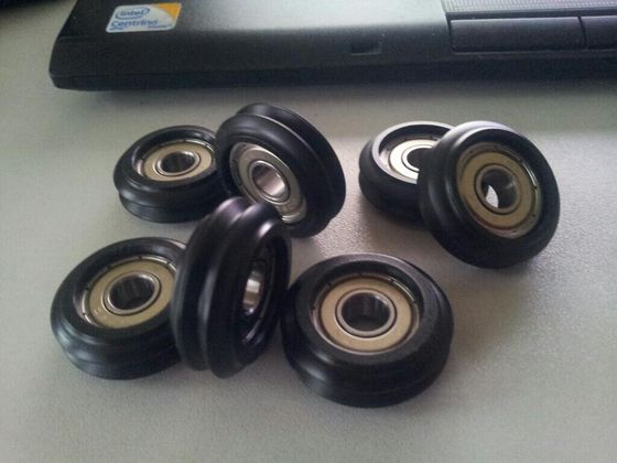
608 bearings with coat/sleeve (Delrin I believe) specially manufactured by Steve Graber on a state-of-the-art CNC lathe. These are at the heart of the vertical movement system used in the Cerberus. Get these babies wrong, and gone is precision & accuracy, and gone is silent movement. I ordered the rollers, idler wheels and filament drive reels at Steve Grabers webshop. Couldn't have done this entire project without those.
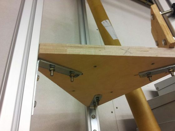
Decided to go with wood instead of printing in PLA, for a host of reasons; Our other printer is in a state of constant testing, rebuilding, breaking and fixing and not deemed production ready yet. Secondly these printed parts are so massive I'd need to babysit our printer for 48 hours or more, even if it doesn't fail halfway. And third, adaptation from imperial to metric proves hard to do, since my extrusions also have a slightly different profile, so it needs a lot more work than just scaling up by 105%, sadly.
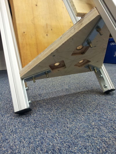
Routed holes for stepper motors
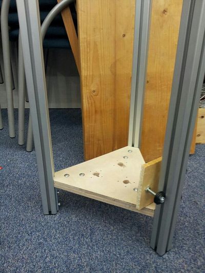
After retrieving my router and making the mounts for the three steppers, I could now bolt it in place in a more permanent fashion. Not too happy with the extrusions not being 100,0% parallel yet, but we're getting there. Robustness though, is already quite good now.
I must await delivery of the stepper motors and must find a way to get the three carriages printed. In the meantime I will find some means to re-make the bottom dual idler mounts and the top idler + tensioner in something other than PLA. So, get creative, Maarten!
Milestone one
My stepper motors have arrived. I mounted them, I filed a notch into the axle to help the set screw grip the axle. All that wasn't very interesting nor hard, so I've included no pics of that.
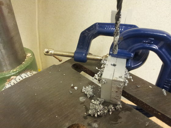
Then I did work on the bottom idlers block, made from thick aluminum and drilled in interesting and difficult ways with the drill press. Bit of trivia: A thick enough piece of aluminum was hard to find, or even near-impossible to find. I wandered around in my local shop until I got lucky in the coat hangers / shelf support aisle: I found a support made of good, thick 8mm aluminum. I even used other parts a bit later on, quite unexpected and quite welcome.
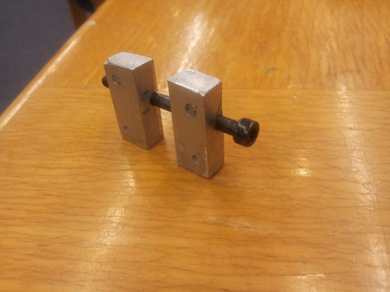
Finished bottom idler support block. I had to specially buy a 4.1 mm drill to make the ID of the idlers a tad larger, because a 4.0mm ID idler does not fit on a 4.0 mm OD rod. Well, it fits, but then you'd need pliers to turn it...
But I really hit a brick wall trying to design the top idler/tensioner. First I attempted something that slid into the gap in the extrusion completely, but I got stuck trying to join two thin aluminum plates to a center piece, without any part or bolt protruding. As it turned out, gluing proved infeasible too; epoxy reportedly can glue metals fine, with the exception of... aluminum. :-(
Then I thought something up: I could use one of the corner round holes to put a threaded rod there, and use a nut to raise it to provide the tensioning mechanism. Then from there the idea developed further and further. Two trips later and I had made it from M5 threaded rod, a partly sawed hinge and some other parts. \o/
It did need some hard, precise and error-prone machining though. It may be interesting to read: As I have very little room in the extrusion, I deployed coach bolts, whose heads I made really thin and flat with a grinder. That was nice but it has obvious drawbacks too of course; I needed to file round the square inset of the shaft too, 'cause that is where my idler would be. And then, finding a ring with ID that fits over that rounded shaft and OD to fit inside the 8mm ID idler... that was a bitch. I could not deploy plastic bushes like you find in electronics, since the plastic against plastic really didn't feel it would run smoothly. I sadly had no immediate source of small pipes/tubes at the time I wanted to test/finish my design. After again a walk through my department store I came to the realization that the aluminum support I had bought as my source of thick aluminum was also equipped with an aluminum rod which measured... 7,7 mm OD. Wow... talk about being lucky! A bit of work with drill, saw, file and caliper and it was done.
Next up was of course threading the whole assembly to make a working proof-of-concept with a single column. Threading the drive-filament proved extremely hard; it is astonishingly hard to try to attach the thin wire in the inside of the column to the nail attached to the carriage, and it is especially hard to get the thread out of a gap next to an idler once it has wedged and pulled itself completely in there. :-(
But the result is there now. It works fine it seems, but I'll have to wait until the stepper can be electronically driven to verify. See these five pics.
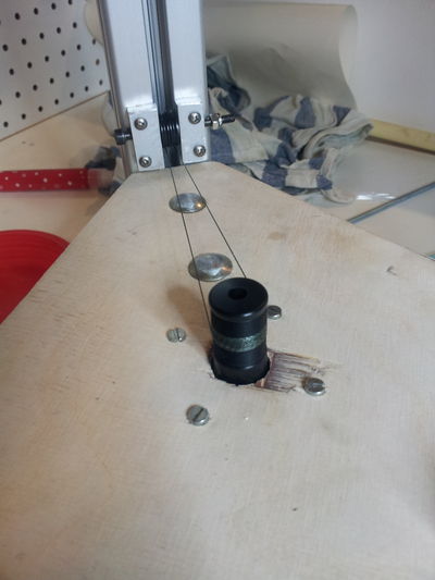
Stepper motor with 9 or 10 windings on axle (axle courtesy of Steve Graber of Grabercars)
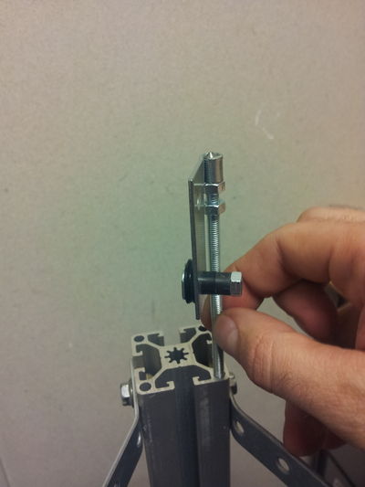
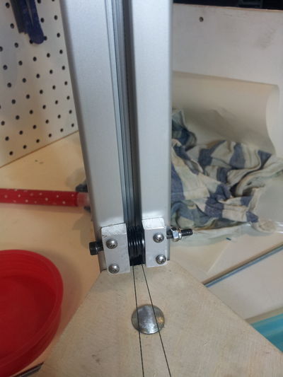
The tensioner with idler wheel
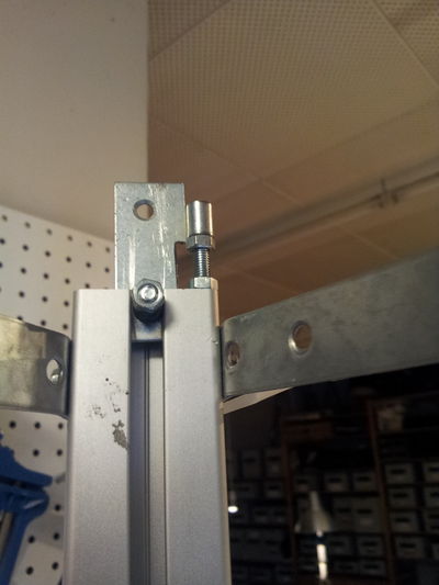
The tensioner with idler wheel inside extrusion
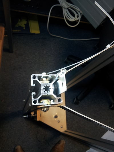
The tensioner with idler wheel inside extrusion, view from top
I asked BuZz of http://nurdspace.nl/Main_Page to print the three carriages and the platform in PLA. They came out excellent. They look a bit bashed now on the pictures but that is because of me filing them, not because they looked this way when delivered. Many thanks, BuZz ! Your printer creates amazing quality stuff!
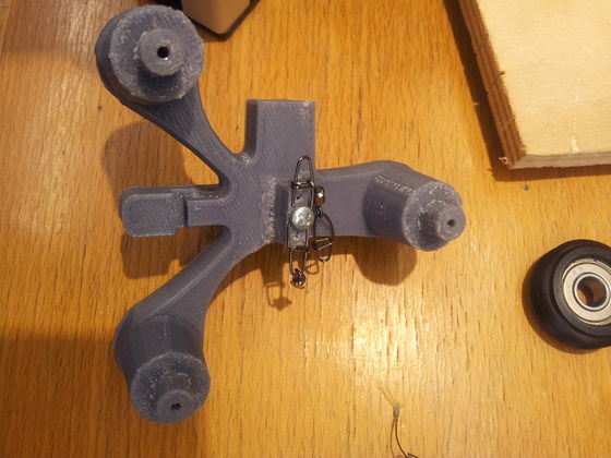
The printed carriages needed a fair bit of filing down due to differences in extrusion profile and the 105% scaling, but still trivial to do. I don't fear it will weaken the construction because the forces work in other directions than which would be risky.
Um, yeah. In case I hadn't mentioned: the original Cerberus parts were made for 1.5" extrusions. I deploy 40mm extrusions. 1.5 inch -> 40mm has a ratio of 1.0498687664 or 1.05x. Hence me printing them at 105% scale.
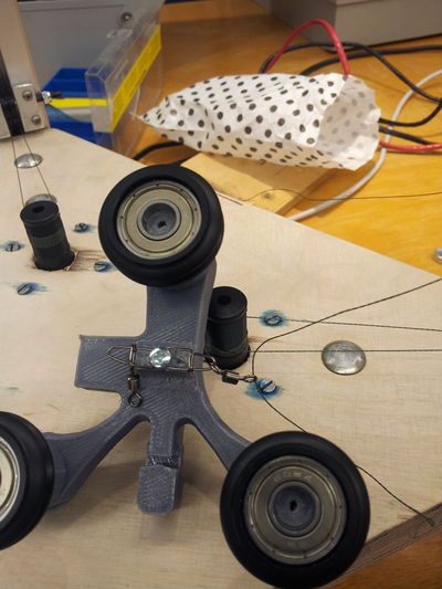
The 65lb fishing gear glands I first got were way too big to fit inside the extrusion cavity so I got smaller ones. I highly doubt the tension would ever really reach such immense levels under normal operating circumstances anyway. Oh and, making the knots is a major pain but with patience and perseverance... even my big clumsy male hands could eventually pull it off.
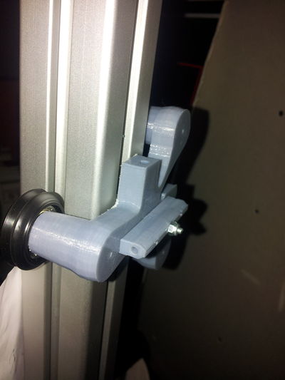
It seems to fit perfectly. A tad on the strained side but I see no ill effect from that. It very efficiently takes away all chances of play, so very very accurate
Milestone two
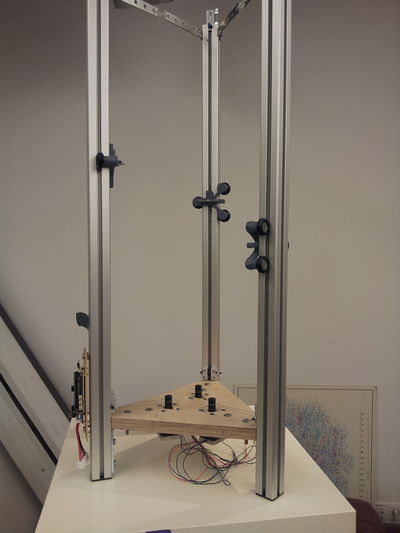
Milestone 2: All three carriages / axis mounted, threaded, moving smoothly, good to go!
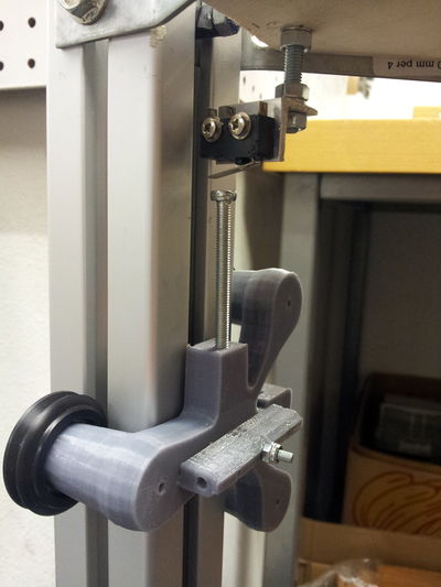
Just normal dependable mechanical endstops, none of this optical endstop blah blah. Mounted on a piece of thread to give the tensioner nut room to move all the way down. Later, I need to engineer it so that the latch of the microswitch doesn't get caught by the slotted screw head when the slot is exactly at a right angle to it. Or simply deploying other screws...
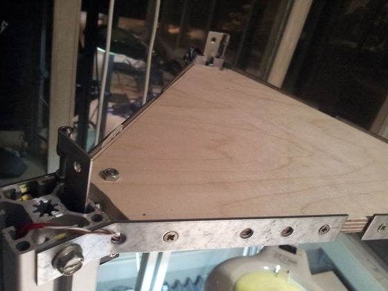
Top bracket also made out of wood. Much better looking than tiewraps!
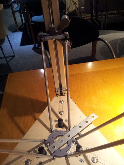
Four of the six arms done and glued. It is very hard to ascertain equal length, this is mainly because there isn't really any endstop anymore on the plastic joints; any that might have been there have been filed down while making it fit the ID of the aluminum tube. I'll do my best, and eventually redo ones that are bad. The two arms aren't exactly parallel, I am therefore thinking of redoing printhead platform joint connections with longer M2 threaded rod + 3mm aluminum tube... And I was about to find out just HOW MUCH those rods really needed to be exactly parallel too...!
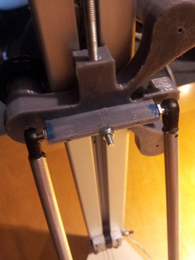
Closeup detail of top joints on carriage. The two-component adhesive I've used is interesting; it literally gives you maybe 120-150 seconds to deploy, after that it has become too hard already to use. Challenging stuff but quite neat and useful 'cause I really really hate to wait for glue to dry!
After all three axis were glued and I started moving the platform around I got quite a scare though. The platform didn't stay level! AT ALL!
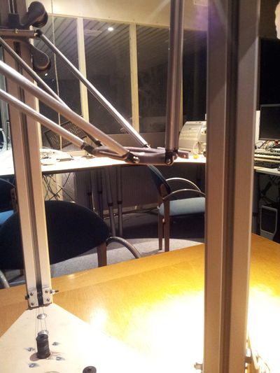
At first I thought that must have been because I reckoned the length of the rods was non-critical provided all six were identical. What stupidity of me ! Now I would have to do them all over :-(
Luckily, a forum pointed me to the real reason; it wasn't the length that was wrong, it was that I neglected to make sure the rods were perfectly parallel; At the top end their distance was wider by quite a margin than at the bottom end. And that -luckily- was far simpler to rectify.
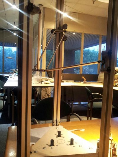
See here the result after rectifying that error. Now the rods are parallel, and the platform stays level throughout its field of movement now!
Filament, Hotend, etc
Today I did expect to receive my new minitronics controller board. But the PostNL mail delivery decided differently :-( Therefore, I spent today making other stuff, spending "too much" time making them too nice and neat, 'cause you need to make time pass... So I made a very nice filament spool holder with actual 608 bearings. And a mounting clamp for the J-head hotend.
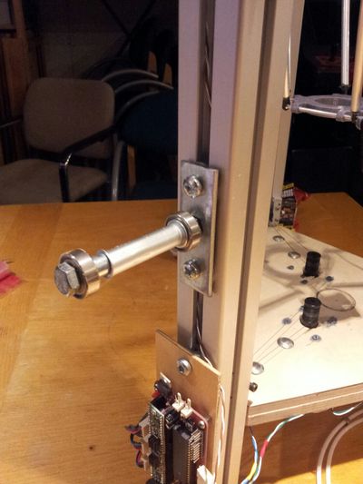
Made this with parts we had in stock. Well except 8mm rings, those I had to scavenge for everywhere: we need to stock up on those. I grinded one nut slightly askew, so the holder is a bit tilted so as to prevent the spool falling off. The extruder (Airtripper direct drive for bowden) will be placed just above this.
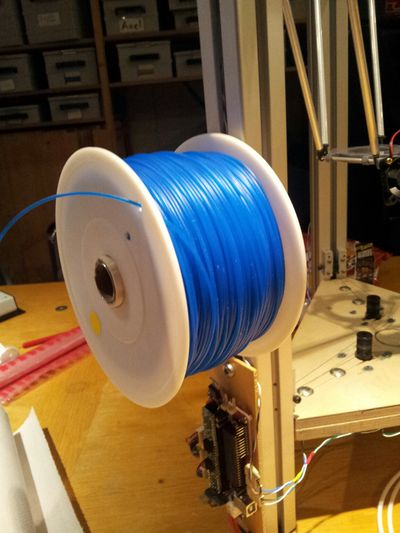
With 1 Kg reel of 1.75 mm filament. The plastic pipe it sits on I had to grind down a very small bit to make it fit into the spool. That was not nice: it is hard to turn down a pipe, even if only by 0.5 mm
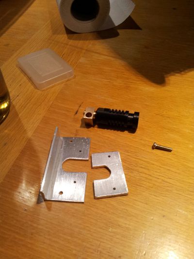
I found two pieces of aluminum that together were exactly the thickness of the slot in the PEEK hotend. Decided to make two U-forms that enclose it completely by placing one reversed. Did this extra-neat with lots of patience, pillar drill, drill fluid, very careful filing, sanding, caliper, etc. It fits like a latex glove around a hand. I use two M2 screws to hold the two halves together but they fit so tight, I'm confident the screws are unnecessary.
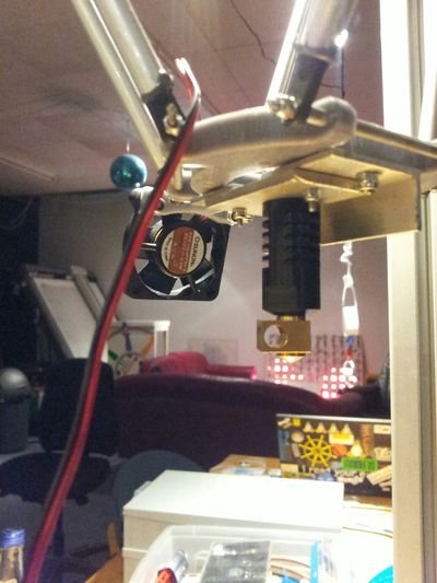
With mounted hotend bracket, J-head 0.5mm-for-1.75mm hotend, PLA cooling fan
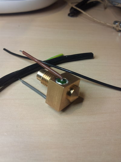
With painstaking precision I rolled I believe some 20-30 layers of aluminum foil around the heater resistor to make it fit very snugly in the channel. I like the result very much, but what a tedious and error-prone job that was...
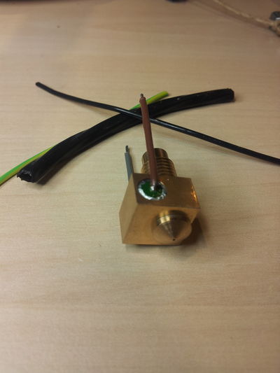
Before you laugh at me and tell me I'm stupid-- no, these aren't plastics around the wires, they're taken from a high temperature proof PTFE wire, you can still see the disassembled pieces of the wire in the immediate background. Will have to run endurance tests still, but first test was passed without a glitch: stuff doesn't start melting, even when heated with soldering iron for 20 seconds.
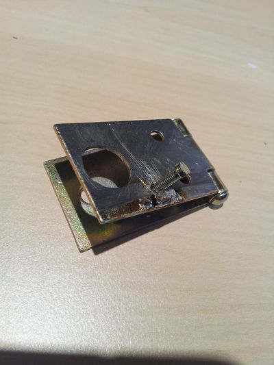
Okay so, some background info first. I use a bowden and a J-Head. Normally the J-Head comes with a hollow set screw to put enough pressure on the PTFE inside to prevent leaking, yet not prevent the PLA from moving by pinching too hard. But in my case, it is highly illogical to end the bowden just above the hotend, cross an air gap, and enter an identical piece of PTFE again inside the J-Head.
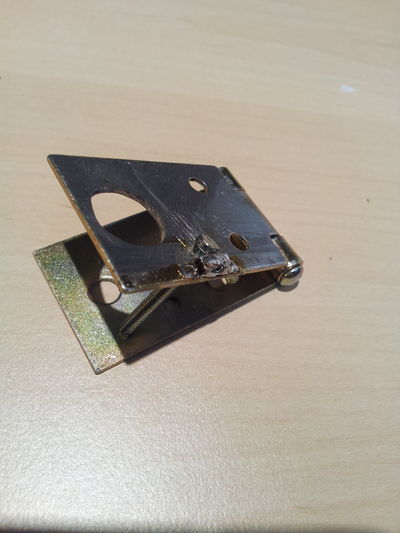
Therefore I had to improvise a bit. I need/want to deploy one continuous bowden PTFE from extruder motor, all the way inside to the hot nozzle. I needed something directly on top of the J-Head to be able to finely adjust the force by which the PTFE is pushed in. Enter a hinge and some drilling and soldering. The screw head is flattened on one side, together with the soldered-on ridge it prevents the screw from turning, yet still enables it to change orientation.
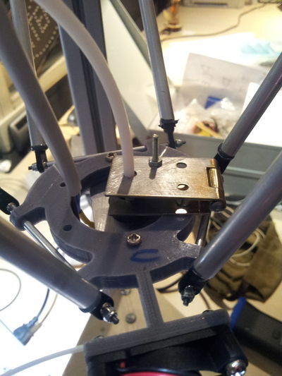
The assembly mounted on the platform. I used two tight-fitting nuts to try and grip the PTFE. We'll have to see how well that stands up to the pressure... Afterwards one needs to drill out the PTFE again with a 2.0 mm drill bit, because the nuts compress it to the point of not being able to pass the filament through the PTFE anymore.
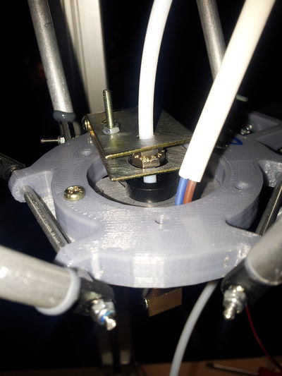
I plan to change the M2.5 nut you see (the adjuster for the pressure) to a wingnut if I'm able to source that. I also still need to devise some way preventing that nut from slowly loosening itself over time with the constant vibrations and movement.
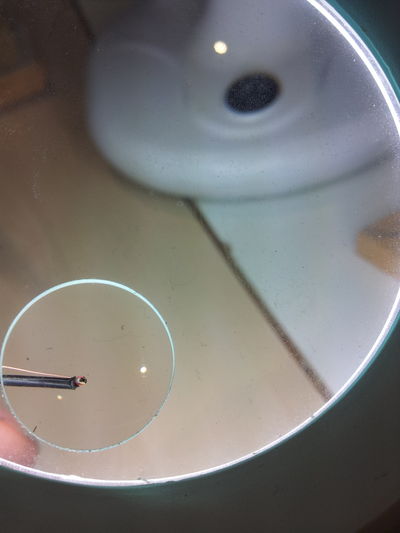
The mounting of the thermistor is, once you start thinking about it, a real challenge. The wires are not insulated, so they will gladly short against each other or against the metal hotend. I possess very thin lacquer-insulated wire but nothing tells me that would withstand 200 degrees Celcius. But it's worse still; one cannot expect a solder joint to hold when the temperature is steady around 200 degrees. And even if one could, the final stretch of wire will still be uninsulated, precisely at the critical spot: inside the tiny 2mm hole. So umm... Kapton tape? meh. Ugly, error prone, flaky. Then I thought of simply just insulating only one of its wires. The hotend isn't electrically connected to anything, so shorting the one wire to it has no effect. And insulating just one wire is very doable; I've used the same PTFE sheath from the dissected wire I used above, only now I made a tiny 1mm incision in the top, so the thermistor can be "half pulled in", making the insulation almost foolproof and greatly simplifying the insertion in its hotend spot too.
Calibration etc
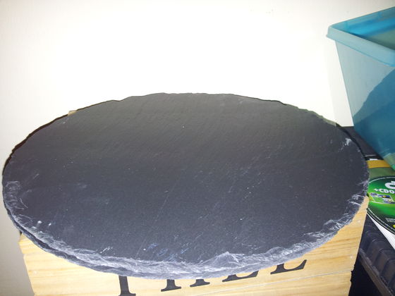
So in a bold and unprecedented move while looking to buy a round glass plate or mirror, I found this piece of slate in a shop. It looks fairly flat, was ridiculously cheap, and I suspect its heat conducting properties are much better than glass. I will try to use this as platform, either with or without a heat source underneath, and either with or without tape to help the PLA adhere. I stand to lose nothing; I can still purchase glass and throw this 3,50 euro investment in the trash if it is really unsuited.
Heh. Well, I used this to try and calibrate, which is a tough job; Sometimes the printer acts erratic, like not reacting to home (G28) commands or moving in random faulty directions, and the math doesn't add up if you recalibrate Z height, strangely enough (if you touch the platform with Z=58 and you decrease MANUAL_Z_HOME_POS with 58, Z=0 *does* *not* touch the platform... Go figure.
I did succeed in at least getting all the numbers nicely close to correct; it now hovers over the platform if I select Z=2, at equal distances in front of all three towers, and it also looks to have the same clearance in the middle. That is great progress compared to yesterday. But a lot of that is still visual, no measurements to back that up. And in hindsight that is a good thing, because the slate looks flat when you look at it with your eye, but when you hold a ruler over it you see very clearly it's not. It has at least 1mm-2mm difference in the middle. So it is a good thing I didn't spend hours precisely tweaking using that as my reference. So further work needs to be done, and a better work surface needs to be acquired.
You can see a short clip of it moving about over here: https://www.youtube.com/watch?v=B0ajfRH5b6k&feature=youtu.be
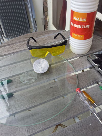
Been looking everywhere for a nice round 30cm glass plate, like in second hand stores, on our local ebay variant, in shops. I also bought some items, like a cheap wall clock which did prove to have a glass faceplate despite that the clerk was adamant it was plastic, and a mirror. But, the glass proved way too thin and had an untreated edge so it was an accident waiting to happen, and the mirror was simply too small. Slowly getting desperate, I found a 30 cm glass cookingware turntable in a Blokker shop. This was in fact, more perfect as I could've imagined; hardened glass, temperature proof, totally smooth edges, extremely flat, virtually unbreakable, and exact the right size. I just had to remove the glued-on center axle/pivot. That proved hard, but possible with extreme force and a lot of solvent to try and weaken the bond...
New Electronics!
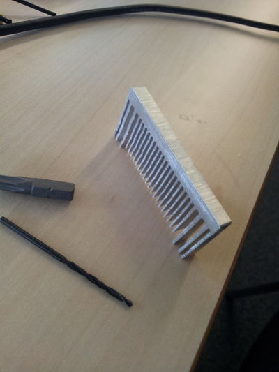
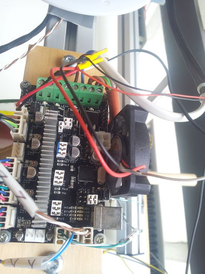
Received Minitronics board from Reprapworld. As I believe in passive cooling I decided to put some sort of heatsink on the stepper drivers. I settled for making one strip that sits on top of all 4 chips, glued on with special heat-conductive glue. The glue took very long to cure, so that made things "interesting". But anyway, this is the heatsink I created by carefully sawing off a slice of an old PC CPU cooler. And pic 2, glued onto the PCB.
The software part -now that I write this, weeks later- is now a bit vague/forgotten. I did make some notes of things that took a while to figure out. One of those is a mention that pins.h needs to be merged, not overwritten. Then there was also a matter of the endstops not properly being defined in there: a delta uses "MAX_ENDSTOP", not "MIN_ENDSTOP". It was either not there, or no actual Arduino pins were properly assigned to these definitions. Until that is fixed, all tinkering with endstop settings in configuration.h is meaningless because they will simply not work and the motor will not stop, trying to push through the endstop, which makes you dash for the power button!
Also a tip: In Pronterface, the translations between XYZ and delta mode have already been done (in firmware). So if you give movement instructions to the X axis motor, you don't just drive the one "X" motor, you would drive all 3(!) motors in order to move the head in the X direction. BUT when you have just wired everything up, some motors will be reversed, adding to the general confusion and you'll not know how to interpret what happens. So here is my tip: forget about X and Y movements! If you click on the Z down or up button, all three motors should move equal amounts, and all in the same direction!. Fix that first by reversing motors (either in software or in hardware) and after that X and Y movement buttons will all of a sudden make much more sense. It took me a while to figure this out, it is completely obvious when you know, but if it is your first time stuff can really be rather opaque to the observer...
Further random tips or observations: slic3r has by default a command to home only the X axis after finishing a print. And by some misunderstood magic, they now mean not some X coordinate somewhere, but simply move the X motor until the X endstop gets hit (so here, this is untranslated, raw XYZ-speak to a delta setup). This is pure evil on a delta, since it will cause the print platform to hit into one of the towers, and keep on headbutting into it until something breaks, or power gets cut off. Remove that command or replace it by a "G28" (home all axis). Do it now. Don't hesitate! You've been warned.
Heating up, extruding
After the calibration I couldn't stop myself from wanting to test the hotend+bowden+heater resistor I made. So I put in the thermistor with the use of some kapton, chose the right value in Configuration.h and very cautiously typed in "M104 S50" and lo and behold, it got warm! After some internal debate about not being able to pull the PLA out cleanly anymore I went and pushed it to 190 degrees and pushed in a length of filament through the bowden tube. And I pressed on. And yep, out it came, a nice thin blue strand of PLA. Whoa. Science, bitches! \o/
Now I really want my extruder...
Movement issues
Aside all this seemingly very good news, there is also bad news. In my enthusiasm I did press for some high speeds and the machine REALLY doesn't cope well with that. It resonates, it routinely shows very weird glitches as if the driving filament is rubber instead of spectra (jumping and hesitating and having severe hiccups and bumps, but still apparently not skipping because the attained end point is still where it is supposed to be (weird). I am unsure if my speed expectations are quite simply too high, or that I need to tweak speed settings so as to try and avoid resonance frequencies, or that the filament is too tight or too loose, the stepper current is too high or too low, some problems with bearings, whatever. Although we did experiment with the tension which didn't show improvement.
Maybe it is more of a software thing and acceleration settings must be tweaked and more intelligent movement commands instead of my crude GCode that tells it to very abruptly stop, change directions, etc. Who knows. But at the moment, it is no speed monster yet...
Success at last!?
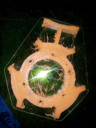
Yay! Tonight marks the first successful print, not counting the 25mm calibration pyramids.
Meltdown!!
Yep, the inevitable happened; My naive belief that the thermistor would stay in its snug hole inside the hotend despite not being glued in there, eventually became a myth. A distinct penetrating smell of molten plastics together with some other worrying effects and now it looks like the hotend ejected itself a bit from the PEEK holder. Ohnoes, it is broken and I have to wait for spare parts to arrive in the mail... Bummer!
But I sorted it out, got a fresh PEEK holder, spent an afternoon taking the whole assembly apart and back together again. I now have the thermistor mounted much better; I could get hold of some awesome micro PTFE insulation tubes, and I deployed some sort of high temp heatsink kit to glue it. Kit is supposed to be fine up to 200 degrees but I'm printing with PLA so I'm not very worried there.
Cheered too soon; more debugging and problemsolving
As can be seen from the first print there was a lot of stringing, but that's only the very beginning of the sorrows...
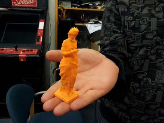
I printed some things fairly successfully, like a statue.
Others were disastrous. The ever-present common factor seemed to be extruder problems. Severe extruder problems. Perimeters went reasonably okay, infill was a disaster. So I adjusted speeds, but it never got to a good point. I had endless trouble. I've had the bowden break loose on two occasions, slippage and skippage, and the motor not turning due to not enough electric energy, etc. I upped current, even to the max the stepper driver could manage, but that didn't solve it. It did necessitate me force-cooling the stepper motor though. I changed the connection of the bowden (now pressfit!) and had to adapt that several times because now the clearings where the filament could (and would) get folded up/jammed were too long. But in the end, I returned to the starting point; having eliminated all weak points in the filament path, it came back to the motor often not being able to develop enough force. It then would not skip or slip no more, just building up pressure in the bowden by "successfully" pushing in filament. Until the point the pressure would overcome the holding force of the stepper, and a stretch of maybe 2 or 3 cm of filament violently came splurting out again, making the extruder stepper make up to a full turn backwards. :-( I experimented with temperature, extrusion multiplier, layer heights, speeds... But nothing I did made any real improvement.
During these times a resident reprap enthusiast told me my layer height of 0.2 mm was probably too high, that my extruder simply couldn't keep up. I tried to print for a while at 0.1 mm, but came to realise that where previous attempts sometimes succeeded, with the layer height at 0.1 mm my success rate dropped to exactly zero %. Extruder couldn't manage it. If I paused a print and lifted the nozzle I could extrude fine, so my conclusion was drawn that 0.1 mm layer height with my 0.5 mm J-Head was simply too hard and the extruder couldn't manage to push out the filament. So then I went for the other extreme, 0.4 layer height. That was a relief: now it extruded again, albeit not nearly enough. Layers were not sticking horizontally nor vertically. I came down to .35 layer height. Still, I had the problem with the extruder getting 'thrown back' every couple seconds. That started not on the first layers, but got worse when prints were under way 3-6 minutes or so, and especially during infill. Sometimes it got so bad that even me "helping" the extruder couldn't manage to push out any plastic... The motor together with me managed to fold-up the filament even in open stretches of no more than 9mm between Mk7 drive wheel and start of PTFE bowden. Incredible but... yea :-(
I was at wit's end. I studied forums, pondered on the problem. Then I did a couple of changes that made a big improvement. I think I know which one was the biggest contributor, but never mind that. 1) I read/saw/heard that Steve Graber used 1/32 microstepping for the axis movement but a "normal" 1/16 microstep driver for the extruder. I got to thinking "What IF that impacts the holding force much??" so I changed jumper settings and changed firmware config. 2) Then, it also struck me that during all this time, the platform fan function was very erratic; it sometimes worked, but more often than not it didn't. I turned it on on occasion by hand with M106, but couldn't quite remember if that impacted the results. I also realized that during the first few weeks that fan was miswired with the effect that is was always on (curiously, coinciding with the prints now being worse than at the beginning). And it dawned on me that most print attempts went fine the first few minutes and then I started to see drying out of plastic supply, which would be consistent with a heating-up problem. All of this hinted at possible clogging due to the PEEK and PTFE getting too hot. So, fed up with it I added M106 in the slic3r pre-print initialization strings as to ensure the fan would really be on at every single print. I also fiddled somewhat in Marlin's Configuration_ADV.h but I daresay that made less of an impact.. if at all.
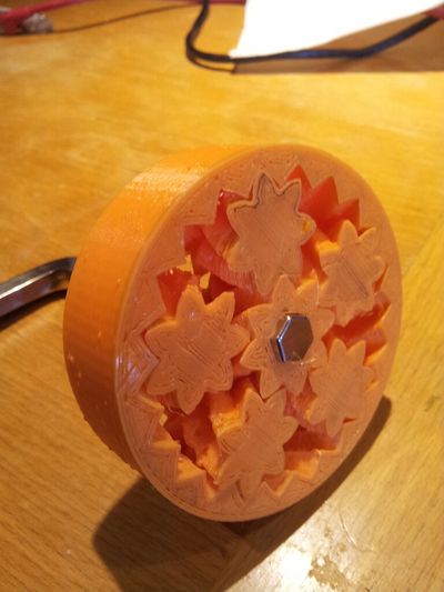
For the umpteenth time I attempted one ballsy print, a planetary gear I found on thingiverse which I had tried to print for a week now. Scaled to 153% and with a very prudent, very conservative 0.66 extruder multiplier. But lo and behold... it printed to completion, and although the layer adhesion is somewhat flaky, it... actually worked; I managed to break the cogs free without damage, it turns nicely without major hiccups and without falling apart. So happy with the results, I proceeded to print two more, with slowly increasing extruder multiplier: 0.73 and 0.77. The extruder performed without a single glitch so far... Yay!
More debugging and problemsolving, Part II
But of course, it didn't end there. Although having the fan on all the time helped, but I still had the aformentioned problems, just less severe on occasion. On a hunch, noticing that it seemed as if the extruder motor sometimes just seemed to stop pushing, and 2 seconds later restarted to work, I figured maybe my gigantic heatsink + cooling fan on the stepper drivers... somehow still wasn't quite enough. So I printed a single-layer-thick object twice; Left, under normal circumstances. Right, with an additional huge high power 150mm fan blowing onto the heatsink/controller board.
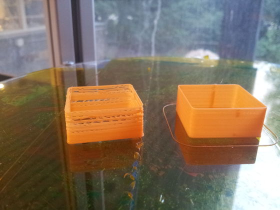
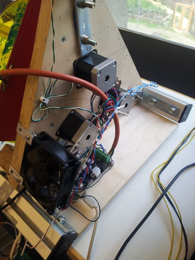
The result was so obvious, so telling that now no doubt remained about the cause of the bad prints: my stepper driver overheated!! So I proceeded to move the controller board to a safer place under the printer, where I could more easily direct a bigger fan onto the heatsink. However, note: This was in a way, a bad move since I've made it almost impossible to turn the stepper driver current adjustments without disassembly. So umm... not that smart. But, it did fix the print issue!
Epilogue
It prints okay now. I did some more adjustments; it turned out the first layer offset was a tad too small, making the extruder slip & skip & jumpback a lot on the first layer, but rarely after that. So that made things better. Also, to my disappointment, I had to lower the speed because otherwise the extruder won't quite keep up. I know the head has no trouble whatsoever to move at 3 times the speed or more, so I'm still looking into fixing the extruder situation in a much more satisfying way. So stay tuned, maybe...
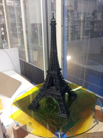
As soon as I thought it worked well enough I attempted to print something really tall. This Eiffel tower was the result. Admittedly not quite high enough at its 29 cm because others had printed 30cm Eiffel towers with their Repraps, I was told quickly.
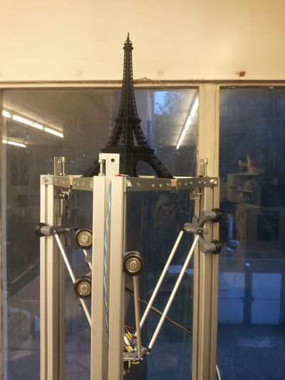
Then, for the occasion of our open day in September, I wanted to showcase something nice for all the visitors so I opted to reprint the Eiffel tower, slightly taller at now 36 cm high. (Taller/bigger proved impossible because I then depassed the max. XY footprint instead of max Z). The agonizing moment was of course when it had to bridge the major gaps... But it turned out, it could.
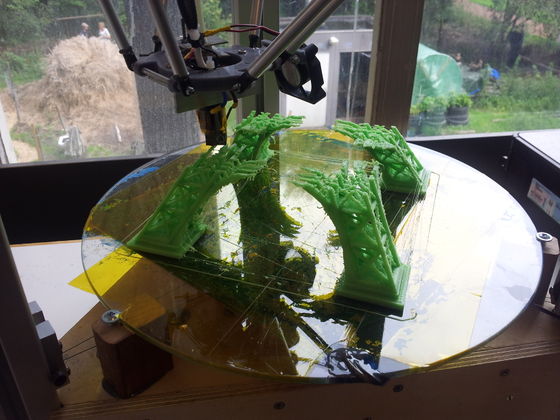
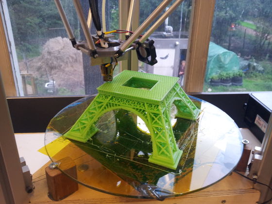
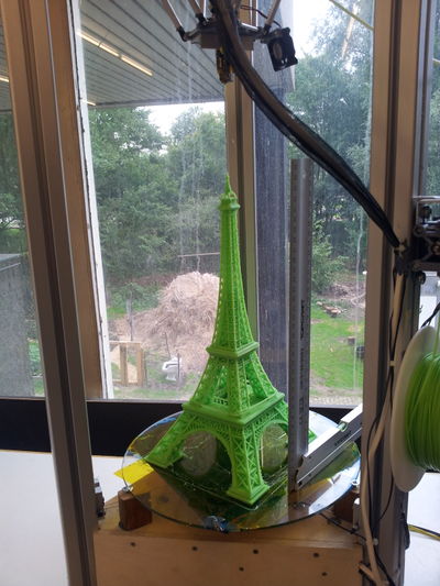
Oh yes: this 36 cm Eiffel tower took from 10 AM to 02 AM to print, so 16 hours overall. I don't know if that is bad or good? It seems relatively slow to me, but it is hard for me to compare...
