2020 Stay The F*** home Techinc Solder Kit: Difference between revisions
Jump to navigation
Jump to search
Brainsmoke (talk | contribs) Created page with "{{Project |ProjectSkills=PCB Design, Soldering |ProjectStatus=Active |ProjectNiche=Electronics |ProjectPurpose=World domination }}" |
Brainsmoke (talk | contribs) No edit summary |
||
| (25 intermediate revisions by the same user not shown) | |||
| Line 1: | Line 1: | ||
{{Project | {{Project | ||
|picture=Techinc_logo_pcb_2020.jpeg | |||
|ProjectSkills=PCB Design, Soldering | |ProjectSkills=PCB Design, Soldering | ||
|ProjectStatus= | |ProjectStatus=Finished | ||
|ProjectNiche=Electronics | |ProjectNiche=Electronics | ||
|ProjectPurpose=World domination | |ProjectPurpose=World domination | ||
}} | }} | ||
== 2020 Stay The F*** Home Techinc Solder Kit == | |||
Following [https://hack42.nl/wiki/Favicoin Hack42] and [https://revspace.nl/Challenge_coin Revspace], Techinc now also has its own 25mm radius round object! Since many of you may suffer from flux-resin withdrawal due to the space being closed, and because the space could do with some extra cash, said round object will be for sale as an SMD solder kit! The kit will include a PCB, a pre-programmed microcontroller, a battery holder, LEDs to taste, a bit of solder (, if requested) and some passives. | |||
I [[User:Brainsmoke|Brainsmoke]], have reimbursed myself for the material costs, the rest of the money will go to the association. | |||
<gallery> | |||
Techinc 2020 pcb top side.jpg|Top side | |||
Techinc 2020 pcb bottom side.jpg|Bottom side | |||
Techinc 2020 pcb in action.jpg|PCB in action | |||
</gallery> | |||
== What does it do? == | |||
* [https://youtu.be/_GvLpknj5m0 Show an animation] | |||
* Show a custom animation sent via 9600 baud UART [8 bytes of brightness values] | |||
The badge can be powered either using a cr2032 battery, or externally, up to 5V. | |||
== What does it cost? == | |||
{| class="wikitable" | |||
|- | |||
! !! product cost | |||
|- | |||
| Techinc 2020 PCB Solder Kit || EUR 10 | |||
|- | |||
| Techinc 2020 PCB already-soldered || EUR 42 | |||
|} | |||
Kits are available at techinc. | |||
== Solder instructions == | |||
[[File:Ti2020instructions.jpg|480px]] | |||
== MCU Code == | |||
https://github.com/brainsmoke/charliepdk | |||
== Driving the LEDs externally using an Arduino == | |||
example program | |||
<pre> | |||
#include <SoftwareSerial.h> | |||
SoftwareSerial s(2, 3); | |||
void setup() | |||
{ | |||
s.begin(9600); | |||
} | |||
uint8_t gamma[256] = { | |||
// gamma = ['{:3d},'.format(int(255*x**2.6 // (255**2.6))) for x in range(256)] | |||
// for i in range(0,256,16): | |||
// print (''.join(gamma[i:i+16])) | |||
0, 0, 0, 0, 0, 0, 0, 0, 0, 0, 0, 0, 0, 0, 0, 0, | |||
0, 0, 0, 0, 0, 0, 0, 0, 0, 0, 0, 0, 0, 0, 0, 1, | |||
1, 1, 1, 1, 1, 1, 1, 1, 2, 2, 2, 2, 2, 2, 2, 3, | |||
3, 3, 3, 3, 4, 4, 4, 4, 4, 5, 5, 5, 5, 6, 6, 6, | |||
7, 7, 7, 7, 8, 8, 8, 9, 9, 9, 10, 10, 10, 11, 11, 12, | |||
12, 12, 13, 13, 14, 14, 15, 15, 16, 16, 17, 17, 18, 18, 19, 19, | |||
20, 20, 21, 21, 22, 22, 23, 24, 24, 25, 26, 26, 27, 27, 28, 29, | |||
30, 30, 31, 32, 32, 33, 34, 35, 35, 36, 37, 38, 39, 39, 40, 41, | |||
42, 43, 44, 45, 46, 46, 47, 48, 49, 50, 51, 52, 53, 54, 55, 56, | |||
57, 58, 59, 60, 61, 63, 64, 65, 66, 67, 68, 69, 71, 72, 73, 74, | |||
75, 77, 78, 79, 80, 82, 83, 84, 86, 87, 88, 90, 91, 92, 94, 95, | |||
97, 98,100,101,103,104,106,107,109,110,112,113,115,117,118,120, | |||
121,123,125,126,128,130,132,133,135,137,139,140,142,144,146,148, | |||
150,152,153,155,157,159,161,163,165,167,169,171,173,175,177,179, | |||
182,184,186,188,190,192,194,197,199,201,203,206,208,210,213,215, | |||
217,220,222,224,227,229,232,234,237,239,242,244,247,249,252,255, | |||
}; | |||
void loop() | |||
{ | |||
uint8_t i; | |||
int k; | |||
for (;;) | |||
{ | |||
for (k=0; k<255; k+=32) | |||
s.write( gamma[(k-i)&0xff] ); | |||
delay(10); | |||
i+=11; | |||
} | |||
} | |||
</pre> | |||
== FAQ == | |||
* '''What MCU is used?''' | |||
''the used MCUs are a Padauk PFS154, or a Padauk PMS150C (depending on availability) | |||
but the design is also pin-compatible with the Attiny2x2 series as well as (some?) SOP8 PIC micros'' | |||
* '''Can the MCU be programmed in-circuit?''' | |||
''Sadly no, but you can display custom animations using a UART rx pin'' | |||
Latest revision as of 14:33, 23 December 2023
| Projects | |
|---|---|

| |
| Participants | |
| Skills | PCB Design, Soldering |
| Status | Finished |
| Niche | Electronics |
| Purpose | World domination |
2020 Stay The F*** Home Techinc Solder Kit
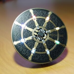
Following Hack42 and Revspace, Techinc now also has its own 25mm radius round object! Since many of you may suffer from flux-resin withdrawal due to the space being closed, and because the space could do with some extra cash, said round object will be for sale as an SMD solder kit! The kit will include a PCB, a pre-programmed microcontroller, a battery holder, LEDs to taste, a bit of solder (, if requested) and some passives.
I Brainsmoke, have reimbursed myself for the material costs, the rest of the money will go to the association.
-
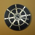
Top side
-
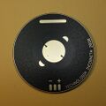
Bottom side
-
PCB in action
What does it do?
- Show an animation
- Show a custom animation sent via 9600 baud UART [8 bytes of brightness values]
The badge can be powered either using a cr2032 battery, or externally, up to 5V.
What does it cost?
| product cost | |
|---|---|
| Techinc 2020 PCB Solder Kit | EUR 10 |
| Techinc 2020 PCB already-soldered | EUR 42 |
Kits are available at techinc.
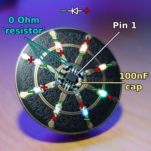
Solder instructions
MCU Code
https://github.com/brainsmoke/charliepdk
Driving the LEDs externally using an Arduino
example program
#include <SoftwareSerial.h>

SoftwareSerial s(2, 3);

void setup()
{
    s.begin(9600);
}

uint8_t gamma[256] = {
// gamma = ['{:3d},'.format(int(255*x**2.6 // (255**2.6))) for x in range(256)]
// for i in range(0,256,16):
//     print (''.join(gamma[i:i+16]))

   0,  0,  0,  0,  0,  0,  0,  0,  0,  0,  0,  0,  0,  0,  0,  0,
   0,  0,  0,  0,  0,  0,  0,  0,  0,  0,  0,  0,  0,  0,  0,  1,
   1,  1,  1,  1,  1,  1,  1,  1,  2,  2,  2,  2,  2,  2,  2,  3,
   3,  3,  3,  3,  4,  4,  4,  4,  4,  5,  5,  5,  5,  6,  6,  6,
   7,  7,  7,  7,  8,  8,  8,  9,  9,  9, 10, 10, 10, 11, 11, 12,
  12, 12, 13, 13, 14, 14, 15, 15, 16, 16, 17, 17, 18, 18, 19, 19,
  20, 20, 21, 21, 22, 22, 23, 24, 24, 25, 26, 26, 27, 27, 28, 29,
  30, 30, 31, 32, 32, 33, 34, 35, 35, 36, 37, 38, 39, 39, 40, 41,
  42, 43, 44, 45, 46, 46, 47, 48, 49, 50, 51, 52, 53, 54, 55, 56,
  57, 58, 59, 60, 61, 63, 64, 65, 66, 67, 68, 69, 71, 72, 73, 74,
  75, 77, 78, 79, 80, 82, 83, 84, 86, 87, 88, 90, 91, 92, 94, 95,
  97, 98,100,101,103,104,106,107,109,110,112,113,115,117,118,120,
 121,123,125,126,128,130,132,133,135,137,139,140,142,144,146,148,
 150,152,153,155,157,159,161,163,165,167,169,171,173,175,177,179,
 182,184,186,188,190,192,194,197,199,201,203,206,208,210,213,215,
 217,220,222,224,227,229,232,234,237,239,242,244,247,249,252,255,
};

void loop()
{
    uint8_t i;
    int k;
    for (;;)
    {
        for (k=0; k<255; k+=32)
            s.write( gamma[(k-i)&0xff] );
        delay(10);
        i+=11;
    }
}
FAQ
* What MCU is used?
  the used MCUs are a Padauk PFS154, or a Padauk PMS150C (depending on availability)
  but the design is also pin-compatible with the Attiny2x2 series as well as (some?) SOP8 PIC micros
* Can the MCU be programmed in-circuit?
  Sadly no, but you can display custom animations using a UART rx pin


