Difference between revisions of "Polyhedrone"
Brainsmoke (talk | contribs) |
Brainsmoke (talk | contribs) |
||
| (35 intermediate revisions by 2 users not shown) | |||
| Line 1: | Line 1: | ||
{{Project | {{Project | ||
|picture=Polyhedronprojectimg.jpg | |picture=Polyhedronprojectimg.jpg | ||
| − | |ProjectSkills=pcb design, | + | |ProjectSkills=pcb design, Golang, maths |
| − | |ProjectStatus= | + | |ProjectStatus=Finished |
|ProjectNiche=Electronics | |ProjectNiche=Electronics | ||
|ProjectPurpose=World domination | |ProjectPurpose=World domination | ||
| Line 10: | Line 10: | ||
=Stage 1: Ledball hardware (completed)= | =Stage 1: Ledball hardware (completed)= | ||
| − | + | == pick a shape == | |
| − | + | A [https://en.wikipedia.org/wiki/Catalan_solid Catalan solid] is a [https://en.wikipedia.org/wiki/Polyhedron polyhedron] with faces which are all identical (but its vertices are not.) | |
| − | + | This is a nice property for a ball made out of PCBs, as you only need to order one shape of PCB. | |
| − | |||
| − | * | + | I Picked the [https://en.wikipedia.org/wiki/Deltoidal_hexecontahedron deltoidal hexecontahedron] because it looked pretty. |
| + | |||
| + | [[File:607px-Deltoidalhexecontahedron.jpg|240px]] | ||
| + | |||
| + | == napkin calculation == | ||
| + | |||
| + | As my ledball should become a flying Death^WDay star at night, I wanted to use lots of LEDs. Powering them over 5V would mean lots of amps. I chose to drive the LEDs per three by putting them in series. This allows the LEDs to be powered reasonably efficiently using 11.1V (3 Cell LiPo) or 12V (ATX PSU.) | ||
| + | |||
| + | This does preclude the use of WS2812B (neopixel) LEDs, so I went for external WS2801 driver chips | ||
| + | |||
| + | * The deltoidal hexecontahedron has 60 faces | ||
| + | * 5 WS2801 drivers per face | ||
| + | * 3 LEDs in series per driver | ||
| + | * max 20mA per colour, 3 colours | ||
| + | |||
| + | >>> 60*5*3*.02 | ||
| + | 18 # Amps | ||
| + | >>> _*12 | ||
| + | 216 # Watt | ||
| + | |||
| + | == Calculate pcb shape == | ||
| + | |||
| + | The code I wrote to generate the PCB shape: | ||
| + | |||
| + | [https://github.com/brainsmoke/dhxdron github.com/brainsmoke/dhxdron] | ||
| + | |||
| + | It generates an SVG shape based on a given radius (of the inscribed sphere) of the polyhedron and the material thickness. The material thickness is used to generate a notched edge which locks at precisely the right angle. | ||
| + | |||
| + | The script also generates slots for the tie-wraps that will hold the ball together. | ||
| + | |||
| + | [[File:Dhxdron-pcbshape.png|480px]] | ||
| + | |||
| + | == Script to generate kicad module from SVG PCB shape == | ||
| + | |||
| + | [https://github.com/brainsmoke/pathtokicad github.com/brainsmoke/pathtokicad] | ||
| + | |||
| + | == Positioning the LEDs == | ||
| + | |||
| + | [[File:Dhxdron-ledpos.png|320px]] [[File:Dhxdron-ledposall.png|320px]] | ||
| + | |||
| + | == KiCAD PCB design == | ||
| + | [https://github.com/brainsmoke/polyhedrone github.com/brainsmoke/polyhedrone] | ||
| + | |||
| + | === Schematic === | ||
| + | |||
| + | [[File:Dhxdron-one-driver.png|320px]] [[File:Dhxdron-board.png|320px]] | ||
| + | |||
| + | === PCB === | ||
| + | |||
| + | [[File:Kicad-polyhedrone.png|480px]] | ||
| + | |||
| + | == Bill of materials == | ||
{| class="wikitable" | {| class="wikitable" | ||
| − | |||
|- | |- | ||
! scope="col"| quantity | ! scope="col"| quantity | ||
| Line 45: | Line 94: | ||
| 1206 | | 1206 | ||
| Resistor 33 Ohm | | Resistor 33 Ohm | ||
| − | | | + | | use 30 Ohm for 20 mA/color (max specced brightness) |
|- | |- | ||
| 300x | | 300x | ||
| Line 56: | Line 105: | ||
| AMS1117-3V3 voltage regulator | | AMS1117-3V3 voltage regulator | ||
| [http://ledsee.com/index.php/voltage-regulators/10-x-ams1117-33v-detail Ledsee] | | [http://ledsee.com/index.php/voltage-regulators/10-x-ams1117-33v-detail Ledsee] | ||
| + | |- | ||
| + | | 1x | ||
| + | | | ||
| + | | Raspberry Pi B+ | ||
| + | |- | ||
| + | | 1x | ||
| + | | | ||
| + | | 200+ Watt (400 Watt) ATX PSU | ||
|} | |} | ||
| + | == Soldering & Testing == | ||
| + | |||
| + | [[File:dhxdron-tester.jpg|480px]] | ||
| + | |||
| + | === Test program === | ||
| + | |||
| + | #include <SPI.h> | ||
| + | |||
| + | void setup() | ||
| + | { | ||
| + | SPI.begin(); | ||
| + | SPI.setBitOrder(MSBFIRST); | ||
| + | SPI.setDataMode(SPI_MODE0); | ||
| + | SPI.setClockDivider(SPI_CLOCK_DIV16); | ||
| + | } | ||
| + | |||
| + | void fill_colour(uint8_t r, uint8_t g, uint8_t b) | ||
| + | { | ||
| + | uint16_t i; | ||
| + | for (i=0; i<500; i++) | ||
| + | { | ||
| + | SPI.transfer(r); | ||
| + | SPI.transfer(g); | ||
| + | SPI.transfer(b); | ||
| + | } | ||
| + | } | ||
| + | |||
| + | void fill_back(uint8_t r, uint8_t g, uint8_t b) | ||
| + | { | ||
| + | uint16_t i; | ||
| + | uint8_t j; | ||
| + | for (i=0; i<100; i++) | ||
| + | { | ||
| + | for (j=0; j<12; j++) | ||
| + | SPI.transfer(0); | ||
| + | |||
| + | SPI.transfer(r); | ||
| + | SPI.transfer(g); | ||
| + | SPI.transfer(b); | ||
| + | } | ||
| + | } | ||
| + | |||
| + | void loop() | ||
| + | { | ||
| + | |||
| + | for(;;) | ||
| + | { | ||
| + | fill_colour(255, 0, 0); // Red | ||
| + | delay(500); | ||
| + | fill_colour(0, 255, 0); // Green | ||
| + | delay(500); | ||
| + | fill_colour(0, 0, 255); // Blue | ||
| + | delay(500); | ||
| + | fill_colour(255, 255, 255); // White | ||
| + | delay(500); | ||
| + | fill_back(255, 0, 0); | ||
| + | delay(500); | ||
| + | fill_back(0, 255, 0); | ||
| + | delay(500); | ||
| + | fill_back(0, 0, 255); | ||
| + | delay(500); | ||
| + | fill_back(255, 255, 255); | ||
| + | delay(500); | ||
| + | fill_colour(0, 0, 0); // Black | ||
| + | delay(500); | ||
| + | } | ||
| + | } | ||
| + | |||
| + | == Wiring == | ||
| + | |||
| + | [[File:Dhxdron-data-path.png|480px]] | ||
| + | |||
| + | == Driving the leds / Power == | ||
| + | |||
| + | For now I use a [[LEDLightDistrict#Raspi_GPIO_pin-out|Raspberry pi]] and an [[LEDLightDistrict#PSU|ATX PSU]] in the same way as for the [[LEDLightDistrict|ledwall]]. | ||
| + | |||
| + | When it is part of a quad copter I'll probably use a Carambola2. | ||
| + | |||
| + | ==pictures== | ||
| + | |||
| + | <gallery heights=160px> | ||
| + | File:Polyhedrone-pcbs.jpg | ||
| + | File:Polyhedrone-unsoldered.jpg | ||
| + | File:FullSizeRender.jpg | ||
| + | File:FullSizeRender(1).jpg | ||
| + | </gallery> | ||
| + | |||
| + | ==Media Coverage== | ||
| + | |||
| + | https://hackaday.com/2016/03/04/polyhedrone/ | ||
| + | |||
| + | |||
| + | =Stage 1.1: Flight case= | ||
| + | |||
| + | (generated with the same script) | ||
| + | |||
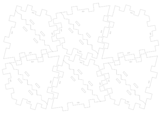
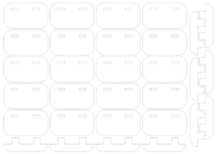
| + | * 8x [[File:Deltoidalhexecontahedronflightcase_faces_8x.svg|320px]] | ||
| + | * 2x [[File:Deltoidalhexecontahedronflightcase split faces 2x.svg|320px]] | ||
| + | * 1x [[File:Deltoidalhexecontahedronflightcase locks 1x.svg|320px]] | ||
==pictures== | ==pictures== | ||
| − | + | <gallery heights=160px> | |
| − | + | File:Deltoidalhexecontahedron-flightcase.jpg | |
| + | File:Deltoidalhexecontahedron-flightcase-half.jpg | ||
| + | </gallery> | ||
=Stage 2: Software (completed)= | =Stage 2: Software (completed)= | ||
Python software: | Python software: | ||
| − | [https://github.com/brainsmoke/dhxlamp github.com/brainsmoke/dhxlamp] | + | [https://github.com/brainsmoke/dhxlamp github.com/brainsmoke/dhxlamp] (obsolete) |
Rewrite in Go: | Rewrite in Go: | ||
[https://github.com/brainsmoke/goled github.com/brainsmoke/goled] | [https://github.com/brainsmoke/goled github.com/brainsmoke/goled] | ||
| + | |||
| + | == Getting the (x, y, z) position of the leds == | ||
| + | |||
| + | [https://github.com/brainsmoke/goled/blob/master/polyhedron/polyhedron.go goled/polyhedron/polyhedron.go] | ||
| + | |||
| + | [https://github.com/brainsmoke/goled/blob/master/model/ledball.go goled/model/ledball.go] | ||
| + | |||
| + | ==pictures== | ||
| + | |||
| + | <gallery heights=160px> | ||
| + | File:dhxdron-dark1.jpg | ||
| + | File:dhxdron-dark2.jpg | ||
| + | File:dhxdron-dark3.jpg | ||
| + | File:dhxdron-dark4.jpg | ||
| + | File:dhxdron-dark5.jpg | ||
| + | File:dhxdron-wobble1.jpg | ||
| + | File:dhxdron-wobble2.jpg | ||
| + | File:dhxdron-patterns1.jpg | ||
| + | File:dhxdron-patterns2.jpg | ||
| + | File:dhxdron-patterns4.jpg | ||
| + | File:dhxdron-fire.jpg | ||
| + | </gallery> | ||
=Stage 3: Make it fly (planning stage)= | =Stage 3: Make it fly (planning stage)= | ||
Latest revision as of 14:41, 23 December 2023
| Projects | |
|---|---|
| |
| Participants | Brainsmoke |
| Skills | pcb design, Golang, maths |
| Status | Finished |
| Niche | Electronics |
| Purpose | World domination |
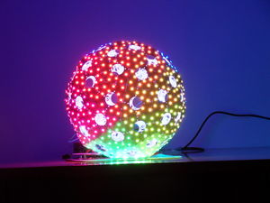
Idea: make a quad copter with lots of addressable RGB LEDs
Contents
- 1 Stage 1: Ledball hardware (completed)
- 2 Stage 1.1: Flight case
- 3 Stage 2: Software (completed)
- 4 Stage 3: Make it fly (planning stage)
Stage 1: Ledball hardware (completed)
pick a shape
A Catalan solid is a polyhedron with faces which are all identical (but its vertices are not.)
This is a nice property for a ball made out of PCBs, as you only need to order one shape of PCB.
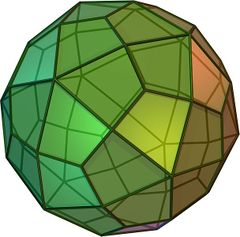
I Picked the deltoidal hexecontahedron because it looked pretty.
napkin calculation
As my ledball should become a flying Death^WDay star at night, I wanted to use lots of LEDs. Powering them over 5V would mean lots of amps. I chose to drive the LEDs per three by putting them in series. This allows the LEDs to be powered reasonably efficiently using 11.1V (3 Cell LiPo) or 12V (ATX PSU.)
This does preclude the use of WS2812B (neopixel) LEDs, so I went for external WS2801 driver chips
- The deltoidal hexecontahedron has 60 faces
- 5 WS2801 drivers per face
- 3 LEDs in series per driver
- max 20mA per colour, 3 colours
>>> 60*5*3*.02
18 # Amps
>>> _*12
216 # Watt
Calculate pcb shape
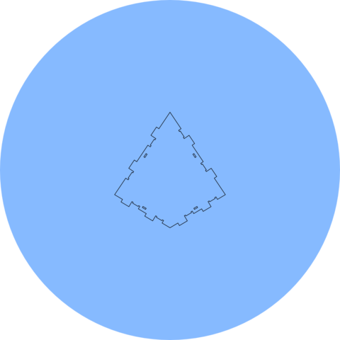
The code I wrote to generate the PCB shape:
It generates an SVG shape based on a given radius (of the inscribed sphere) of the polyhedron and the material thickness. The material thickness is used to generate a notched edge which locks at precisely the right angle.
The script also generates slots for the tie-wraps that will hold the ball together.
Script to generate kicad module from SVG PCB shape
github.com/brainsmoke/pathtokicad
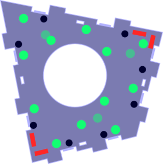
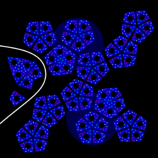
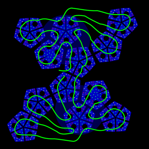
Positioning the LEDs
KiCAD PCB design
github.com/brainsmoke/polyhedrone
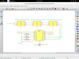
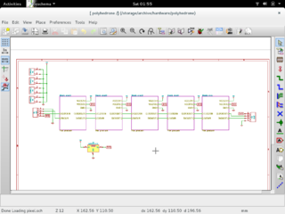
Schematic
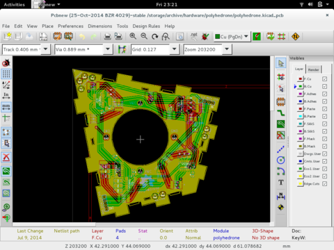
PCB
Bill of materials
| quantity | package | part | comment |
|---|---|---|---|
| 60x | PCB | ordered 100x 2 layer, 10^2cm max, .6mm, white HASL @ Seeedstudio | |
| 300x | SOIC14 | WS2801 Led Driver | Ledsee |
| 900x | 5050 | RGB LED SMD | ordered: 1000x Samsung SPMFCT5606N0S0A1E0 (Nice color balance) @ Ledsee |
| 900x | 1206 | Resistor 33 Ohm | use 30 Ohm for 20 mA/color (max specced brightness) |
| 300x | 0805 | 100nF Capacitor | |
| 12x | SOT223 | AMS1117-3V3 voltage regulator | Ledsee |
| 1x | Raspberry Pi B+ | ||
| 1x | 200+ Watt (400 Watt) ATX PSU |
Soldering & Testing
Test program
 #include <SPI.h>

 void setup()
 {
     SPI.begin();
     SPI.setBitOrder(MSBFIRST);
     SPI.setDataMode(SPI_MODE0);
     SPI.setClockDivider(SPI_CLOCK_DIV16);
 }

 void fill_colour(uint8_t r, uint8_t g, uint8_t b)
 {
     uint16_t i;
     for (i=0; i<500; i++)
     {
         SPI.transfer(r);
         SPI.transfer(g);
         SPI.transfer(b);
     }
 }

 void fill_back(uint8_t r, uint8_t g, uint8_t b)
 {
     uint16_t i;
     uint8_t j;
     for (i=0; i<100; i++)
     {
         for (j=0; j<12; j++)
             SPI.transfer(0);

         SPI.transfer(r);
         SPI.transfer(g);
         SPI.transfer(b);
     }
 }

 void loop()
 {

     for(;;)
     {
         fill_colour(255, 0, 0);     // Red
         delay(500);
         fill_colour(0, 255, 0);     // Green
         delay(500);
         fill_colour(0, 0, 255);     // Blue
         delay(500);
         fill_colour(255, 255, 255); // White
         delay(500);
         fill_back(255, 0, 0);
         delay(500);
         fill_back(0, 255, 0);
         delay(500);
         fill_back(0, 0, 255);
         delay(500);
         fill_back(255, 255, 255);
         delay(500);
         fill_colour(0, 0, 0);        // Black
         delay(500);
     }
 }
Wiring
Driving the leds / Power
For now I use a Raspberry pi and an ATX PSU in the same way as for the ledwall.
When it is part of a quad copter I'll probably use a Carambola2.
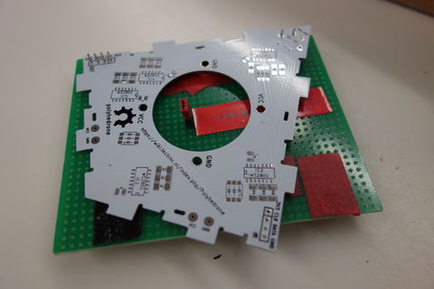
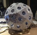
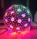
pictures
Media Coverage
https://hackaday.com/2016/03/04/polyhedrone/
Stage 1.1: Flight case
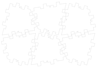
(generated with the same script)
pictures
Stage 2: Software (completed)
Python software: github.com/brainsmoke/dhxlamp (obsolete)
Rewrite in Go: github.com/brainsmoke/goled
Getting the (x, y, z) position of the leds
goled/polyhedron/polyhedron.go
