Difference between revisions of "Cerberups"
m |
m |
||
| Line 90: | Line 90: | ||
Closeup detail of top joints on carriage <br><br> | Closeup detail of top joints on carriage <br><br> | ||
| − | After all three axis were glued and I started moving the platform around I got quite a scare though. | + | After all three axis were glued and I started moving the platform around I got quite a scare though. ''The platform didn't stay level!'' '''AT ALL!''' <br><br> |
| − | [[File:20130530 | + | [[File:20130530 040904.jpg|400px]]<br> |
| − | I | + | At first I thought that must have been because I reckoned the length of the rods was non-critical provided all six were identical. '''''What stupidity of me !''''' Now I would have to do them all over ''':-(''' <br> |
| − | Luckily, a forum pointed me to the real reason; it wasn't the length, it was that I neglected to make sure the rods were perfectly parallel; the top end was wider by quite a margin than the bottom end. And that was | + | Luckily, a forum pointed me to the real reason; it wasn't the length that was wrong, it was that I neglected to make sure the rods were perfectly parallel; At the top end their distance was wider by quite a margin than at the bottom end. And that -luckily- was far simpler to rectify.<br><br> |
[[File:horizontalagain.jpg|400px]]<br> | [[File:horizontalagain.jpg|400px]]<br> | ||
Revision as of 05:08, 30 May 2013
| Projects | |
|---|---|
| Participants | Ultratux |
| Skills | Woodworking, precision assembly, electronics, fine mechanic |
| Status | Active |
| Niche | Mechanics |
| Purpose | World domination |
Introduction
Cerberups, a Delta-type 3D printer. It is a slight modification to a US design, the Cerberus, see https://github.com/grabercars/Cerberus. My modifications were mainly necessary to adapt from imperial to metric extrusions, but also because other choices were made in type of materials (ie. wood instead of PLA). The Cerberus itself is based on the Rostock, of course: the first delta 3D printer.
First steps
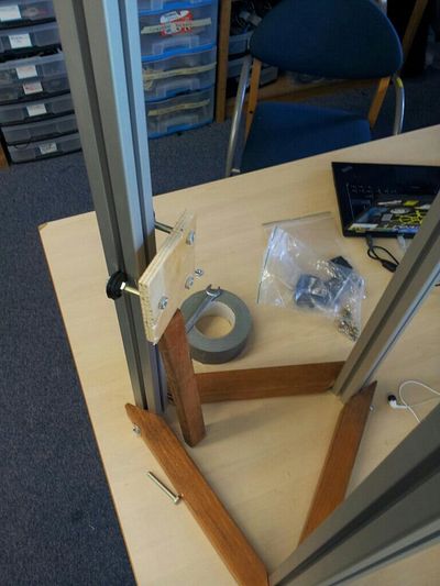
First uneasy steps. This was rather hard; the used wood is a very hard and tough kind. And it's only when you need a 30 degree angle, you find that none of our tools have any setting for it, or they are so coarse/imprecise as to be completely useless... Examples: I wanted to buy a mitre box with a 30 & 60 degree cut-- unobtainable. And our mitre saw has a 60 degree angle, but can't manage 30 degrees... Oh well. Lots of improvisation. Lots of extensive postwork on the very resistant wood...
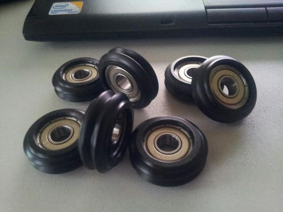
Coating specially crafted by Steve Graber (the designer of the Cerberus) on his state-of-the-art CNC lathe. These are at the heart of the vertical movement system used in the Cerberus. Get these babies wrong, and gone is precision & accuracy, and gone is silent movement.
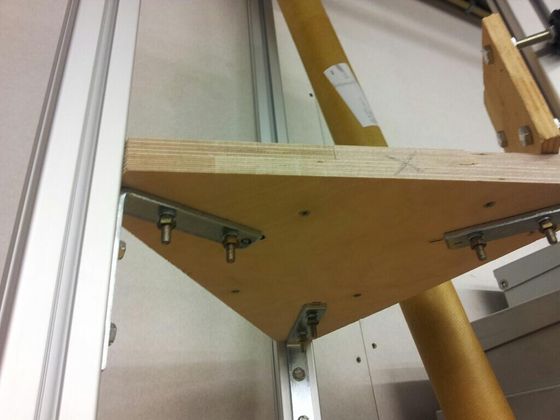
Decided to go with wood instead of printing in PLA, for a host of reasons; Our other printer is in a state of constant testing, rebuilding, breaking and fixing and not deemed production ready yet. Secondly these printed parts are so massive I'd need to babysit our printer for 48 hours or more, even if it doesn't fail halfway. And third, adaptation from imperial to metric proves hard to do, since my extrusions also have a slightly different profile, so it needs a lot more work than just scaling up by 105%, sadly.
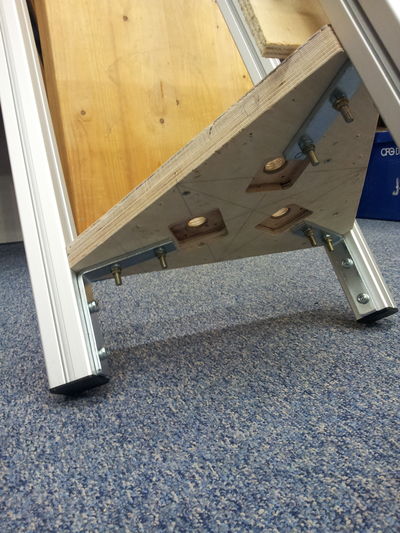
Routed holes for stepper motors
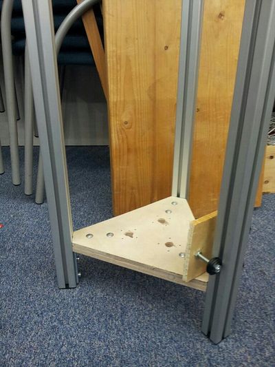
After retrieving my router and making the mounts for the three steppers, I could now bolt it in place in a more permanent fashion. Not too happy with the extrusions not being 100,0% parallel yet, but we're getting there. Robustness though, is already quite good now.
I must await delivery of the stepper motors and must find a way to get the three carriages printed. In the meantime I will find some means to re-make the bottom dual idler mounts and the top idler + tensioner in something other than PLA. So, get creative, Maarten!
Milestone one
My stepper motors have arrived. I mounted them, I filed a notch into the axle to help the set screw grip the axle. All that wasn't very interesting nor hard, so I've included no pics of that.
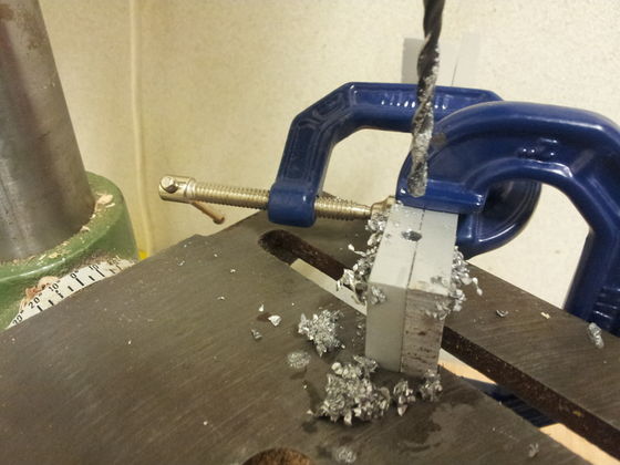
Then I did work on the bottom idlers block, made from thick aluminum and drilled in interesting and difficult ways with the drill press.
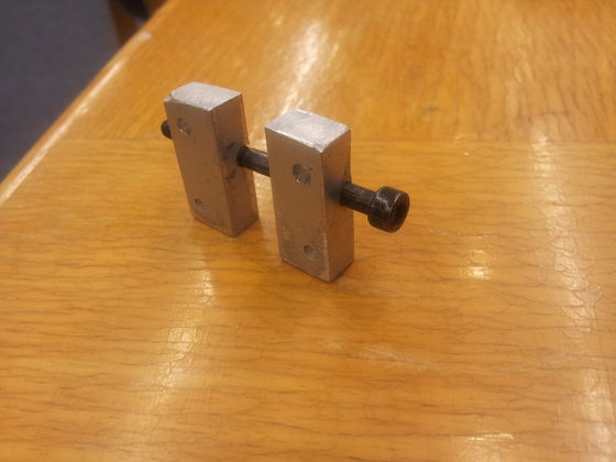
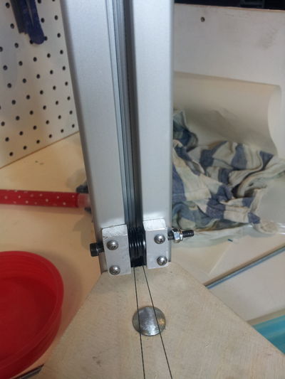
Finished bottom idler support block
But I really hit a brick wall trying to design the top idler/tensioner. First I attempted something that slid into the gap in the extrusion completely, but I got stuck trying to join two thin aluminum plates to a center piece, without any part or bolt protruding. As it turned out, gluing proved infeasible too; epoxy reportedly can glue metals fine, with the exception of... aluminum. :-(
Then I thought something up: I could use one of the corner round holes to put a threaded rod there, and use a nut to raise it. Then from there the idea developed further and further. Two trips to Gamma and I had made it from M5 threaded rod, a partly sawed hinge and some other parts. \o/
Next up was of course threading the whole assembly to make a working proof-of-concept with a single column. Threading the drive-filament proved extremely hard; it is astonishingly hard to try to attach the thin wire in the inside of the column to the nail attached to the carriage, and it is especially hard to get the thread out of a gap next to an idler once it has wedged and pulled itself completely in there. :-(
But the result is there now. It works fine it seems, but I'll have to wait until the stepper can be electronically driven to verify. See these four pics.
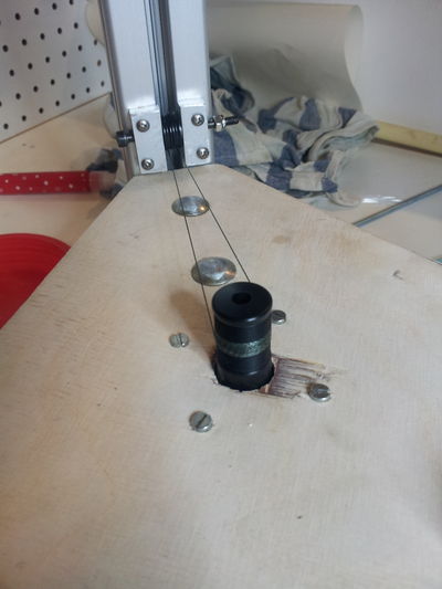
Stepper motor with 9 or 10 windings on axle
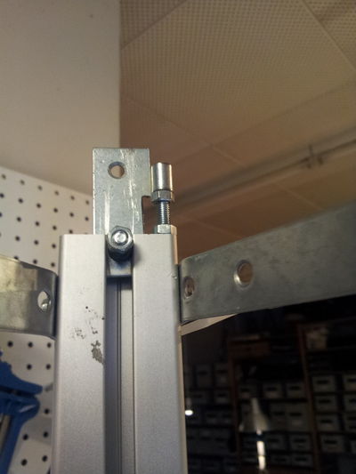
The tensioner with idler wheel inside extrusion
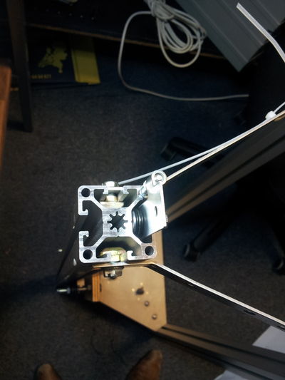
The tensioner with idler wheel inside extrusion, view from top
I asked BuZz of Nurdspace to print the three carriages and the platform in PLA. They came out excellent. They look a bit bashed on the pictures but that is because of me filing them, not because they looked this way when delivered. Many thanks, BuZz !
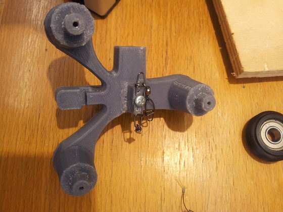
The printed carriages needed a fair bit of filing down due to differences in extrusion profile and the 105% scaling, but still trivial to do
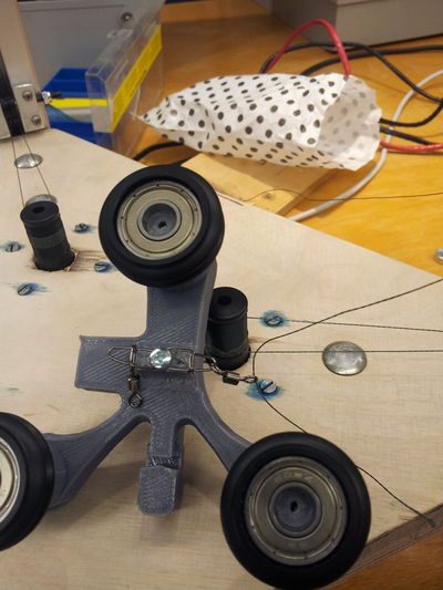
The 65lb fishing gear glands I first got are way too big to fit so I got smaller ones. I highly doubt the tension would ever really reach such immense levels under normal operating circumstances anyway. Oh and, making the knots is a major pain
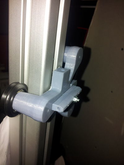
It seems to fit perfectly. A tad on the strained side but I see no ill effect from that. It very efficiently takes away all chances of play, so very very accurate
Milestone two
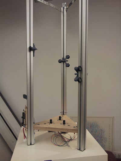
Milestone 2: All three carriages / axis mounted, threaded, moving smoothly, good to go!
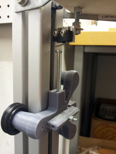
Just normal dependable mechanical endstops, none of this optical endstop blah blah. Mounted on a piece of thread to give the tensioner nut room to move all the way down.
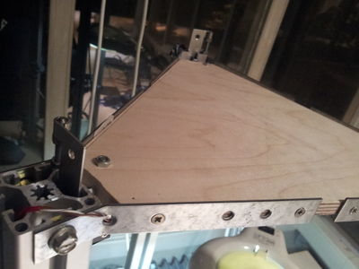
Top bracket also made out of wood. Much better than tiewraps!
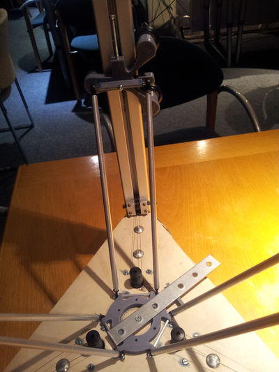
Four of the six arms done and glued. It is very hard to ascertain equal length, this is mainly because there isn't really any endstop anymore on the plastic joints; any that might have been there have been filed down while making it fit the ID of the aluminum tube. I'll do my best, and eventually redo ones that are bad. The two arms aren't exactly parallel, I am therefore thinking of redoing printhead platform joint connections with longer M2 threaded rod+aluminum tube...
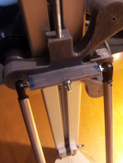
Closeup detail of top joints on carriage
After all three axis were glued and I started moving the platform around I got quite a scare though. The platform didn't stay level! AT ALL!
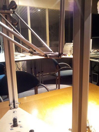
At first I thought that must have been because I reckoned the length of the rods was non-critical provided all six were identical. What stupidity of me ! Now I would have to do them all over :-(
Luckily, a forum pointed me to the real reason; it wasn't the length that was wrong, it was that I neglected to make sure the rods were perfectly parallel; At the top end their distance was wider by quite a margin than at the bottom end. And that -luckily- was far simpler to rectify.
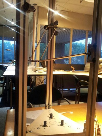
See here the result after rectifying that error. Now the rods are parallel, and the platform stays level throughout its field of movement now!
