Difference between revisions of "Laser-pop"
| Line 2: | Line 2: | ||
|picture=Laserpop 0914 .jpg | |picture=Laserpop 0914 .jpg | ||
|ProjectSkills=Electronics, Arduino, | |ProjectSkills=Electronics, Arduino, | ||
| − | |ProjectStatus= | + | |ProjectStatus=Dormant |
|ProjectNiche=Electronics | |ProjectNiche=Electronics | ||
|ProjectPurpose=Fun | |ProjectPurpose=Fun | ||
Latest revision as of 01:51, 15 February 2017
| Projects | |
|---|---|

| |
| Participants | Chotee |
| Skills | Electronics, Arduino |
| Status | Dormant |
| Niche | Electronics |
| Purpose | Fun |
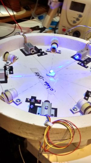
Project to make popcorn with lasers.
Contents
Global status
Not popping (yet). It does create corns with multiple burned holes in them.
Project Design Goal
A single corn gets dropped from a hopper onto a hotseat. five one Watt lasers shine on the corn-kernel. The force of the corns-husk failing critically and spilling it's boiling insides (the pop) makes the corn jump out of the hot seat, falling into a tray for consumption. A new corn will be taken from the corn hopper.
Laser Diodes
The lasers are Casio M140 Diodes. They are known to run at 1 Watt output. There are reports of running them at 2 Watt output, but life-expectancy will be much lower. This project will run them at the conservative 1W.
The light produced is 445nm. Which is blue pushing into the ultraviolet.
Stern warning:: These are class 4 Lasers. 1 watt of light concentrated into 1mm² does very bad things to eyes, very, very quickly. So fast that the fastest human reflexes are completely inadequate. If you ever work with this project without the covers in place, always use appropriate eye-protection whenever the lasers could possibly be powered on. Two pair of protective glasses can always be found near the project. Use them.
Be aware of reflections. Metal objects, like jewellery, can make great mirrors. Take them off when working with lasers. Before firing the lasers, ask yourself, where the beam is going to hit, and how the reflection will be.
Even when using the correct eye-wear, never look into a laser on purpose. Be aware of other people that might in line of sight of the project.
Don't circumvent the lockouts. They are there for a reason.
Power supplies
The power comes from the mains via a normal PC power supply.
- +5V is used for the lasers. Expected max is 5*1.5A = 7.5A
- +12V is used for Ardunio and opamp logic. Current negligible, maybe 100mA
Laser power
Lasers need constant current power supplies. Laser diodes have a Negative Temperature Coefficient. When warming up, they will have less resistance. thus draw more current, heating up even more, etc. Eventually burning themselves up. A constant current supply is thus needed.
Each of the lasers is individually controllable. So 5 constant current supplies that can give run 1.5A each. At 1.2A the lasers require 4.45V. Since the idea is to use the 5V power rail of the PC power supply. A low dropout linear voltage regulator is needed. The LT3086 has a dropout of only 330mV and supports up to 2.5A of current. Making it ideal for this application.
Thermal issues
There's a lot of wasted heat. Both the laser-diode and the power supplies will need to be heat-sunk and temperature monitored. Each laser has a 9701A thermometer mounted directly on the diode to measure that temperature. The linear rectifieres (LT3086) have an internal temperature sensor, making it easy to measure as well.
Beam capture
To detect that the beam is not being obstructed by the corn-kernel, a light-sensitive diode is used This diode detects light bouncing off the back wall of a light "capture" device. The diode should drop it's electrical resistance to near Zero in a few micro-seconds after the light hits the back wall. Indicating to the Arduino the beam is not obstructed.
The backwall of the sink is a 5 euro-cent coin spray-painted with high-temperature resistant black coating. The coins are a known weight 3.91g and known material, copper covered steel. By thermo-isolating the backwall and attaching a thermometer to it, it is possible to typify performance differences and degradation over time of the laser diodes with reasonable accuracy.
The sides of the beam capture will be semi-transparent plastics that will light up by the light being refracted on the back wall.
Laser heads
Contains the laser-diode inside a heat-sink.
There are 5 lasers, so 5 times all of the following.
- M140 Laser Diode. Can be sourced via EBay.
- Copper mount
- Laser housing
- Glass lenses for 445nm light. The standard platic ones will fail with this level of lasers.
- Aluminium Housing
- MCP9701A temperature sensor heat-shrunk directly on the back of laser diode.
The laser Housing, lenses etc. where sourced from AixiZ.com
Constant current Source
For supplying the constant current to the Laser diodes, a circuit was made. It uses an LT3086 Linear Regulator and a LM324 Quad op-amp.
The design uses a +5V rail for driving the laser and a +12V for rail for the op-amp circuits.
A PCB was designed and printed with http://dirtypcbs.com/
Laser Aimer
Light sink
Bom
- 10x MCP9701A (5 mounted on each laser diode, 5 mounted behind each backwall)
- 5 Constant current sources
- 1x Arduino Mega
- 1x Tablet for user interface.