Difference between revisions of "LEDLightDistrict"
Brainsmoke (talk | contribs) |
|||
| (51 intermediate revisions by 7 users not shown) | |||
| Line 1: | Line 1: | ||
{{Project | {{Project | ||
| + | |picture=ledwall_dark.jpg | ||
|ProjectSkills=soldering,coding | |ProjectSkills=soldering,coding | ||
| − | |ProjectStatus= | + | |ProjectStatus=Finished |
|ProjectNiche=Electronics | |ProjectNiche=Electronics | ||
|ProjectPurpose=World domination | |ProjectPurpose=World domination | ||
}} | }} | ||
| − | + | The Led wall continues its life as our [[Fireplace]] | |
| − | + | Project to LED'ify <del>the outside facing glass 'block' wall. each glass box will be a pixel</del> the space | |
| − | = | + | == The device == |
| − | + | the Led-wall is currently housed in a surround that makes it look more like a proper fire-place; made of MDF , created by [[User:milo]] [[user:justa]] [[user:einstein]] for use on the UrbanResort open day of 20130921. | |
| − | + | It's been fited with a set of switches on the left hand side that operate the functions of the led-wall and/or a power-bar mounted inside the left-most column of the fireplace. | |
| − | + | The power-bar is supplied so that you can turn on any lamps or other 'peripherals' belonging to the fireplace with one simple action. | |
| − | + | When turning on the fireplace, please allow one minute for the RaspPI to boot. It loads the firmware from an SD card and is not 'insta-on' | |
| − | + | it will automatically start doing the fire. to run the all the animations | |
| + | |||
| + | sudo bash ; cd /home/erik/lewd/src ; python ledshow.py -spi | ||
| − | + | ||
| + | === Doesn't work! === | ||
| + | |||
| + | * log in to [[ledwall]] using the user techinc (pw is same as the wifi) | ||
| + | * <code>git checkout https://github.com/techinc/lewd.git</code> | ||
| + | * <code>for the C fireplace: cd c ; ./fire /dev/spidev0.0 (should be started automatically by /etc/rc.local)</code> | ||
| + | * <code>for the python implementation: cd src ; python ledshow.py -spi</code> | ||
| + | |||
| + | == Hardware == | ||
| + | |||
| + | === Design === | ||
| + | |||
| + | ==== Overview ==== | ||
| + | |||
| + | <strong>Raspberry Pi</strong> ===(SPI)===> <strong>ledwall</strong> | ||
| + | ^ ^ | ||
| + | | (5V) | (12V) | ||
| + | \----------<strong>PSU</strong> ---------/ | ||
| + | |||
| + | ==== Raspi GPIO pin-out ==== | ||
| + | |||
| + | The code uses the hardware SPI present on the the Raspberry Pi. | ||
| + | |||
| + | * <span style="color: green; font-weight: Bold;">Green wire</span> on <strong>Pin 23</strong> is <strong>Clock (SCLK)</strong> | ||
| + | * <span style="color: #dddd11; font-weight: Bold;">Yellow wire</span> on <strong>Pin 19</strong> is <strong>Data (MOSI)</strong> | ||
| + | * <span style="color: black; font-weight: Bold;">Black wire</span> <strong><del>should be connected to a ground pin.</del> does not have to be connected to the ground pin, not having a common ground works as well, and doesn't generate noise.</strong> | ||
| + | * <span style="color: red; font-weight: Bold;">Red wire</span> <strong>should NOT be connected to the Raspi as it will break it!</strong> | ||
| + | |||
| + | [[Image:raspi_spi.jpg|480px]] | ||
| + | |||
| + | [[Image:raspi_casing.jpg|480px]] | ||
| + | |||
| + | ==== PSU ==== | ||
| + | |||
| + | [[Image:Ledwall_ATX.jpg|480px]] | ||
| + | |||
| + | There I fixed it X-/ | ||
| + | |||
| + | [[Image:Ledwall_molex_thereifixedit.jpg|480px]] | ||
| + | |||
| + | == Software == | ||
| + | |||
| + | == Software Implementations == | ||
| + | |||
| + | [https://github.com/techinc/lewd The current python based implementation called | ||
| + | lewd] runs | ||
| + | on the machine connected to the LED-Wall over a serial port. | ||
| + | |||
| + | The older [https://github.com/techinc/LedWallServer javascript node.js version] | ||
| + | can communicate with the python implementation to push frames to the LED-Wall | ||
| + | using TCP sockets. | ||
Python documentation (temporary location) http://old.villavu.com/merlijn/lewd | Python documentation (temporary location) http://old.villavu.com/merlijn/lewd | ||
| − | == | + | === Lewd === |
| + | |||
| + | The Python (lewd) implementation features several backends. '''-serial''', | ||
| + | '''-spi''', '''-net''' and '''-local''' (which renders on an SDL screen). | ||
| + | |||
| + | See the file "ledwall.py" for an example on how to use all these different | ||
| + | LedWall frontends. At the space, you should typically use RemoteLedScreen to | ||
| + | interface with the (already running) server to the LEDWall. | ||
| + | |||
| + | To just play around with the code locally, look into the VirtualLedScreen code; | ||
| + | you will need to install pygame to actually use the local UI. | ||
| + | |||
| + | ==== Python documentation (temporary location) ==== | ||
| + | |||
| + | http://old.villavu.com/merlijn/lewd | ||
| + | |||
| + | == Photos & Videos == | ||
| + | <gallery heights=150px> | ||
| + | File:Ledwall1.0-leds-spooned.jpg | ||
| + | File:Ledwall2.0-mount.jpg | ||
| + | File:ledwall.jpg | ||
| + | File:ledwall_dark.jpg | ||
| + | File:ledwall_arduino_pinout.jpg | ||
| + | File:Techinc_Hearth.jpg | ||
| + | </gallery> | ||
| + | |||
| + | == OLD == | ||
| + | |||
| + | === Alternative configuration using Arduino (Obsolete) === | ||
| + | |||
| + | <strong>computer</strong> ===(serial over usb)===> <strong>arduino</strong> ===(SPI)===> <strong>ledwall</strong> | ||
| + | ^ | ||
| + | | (12V) | ||
| + | <strong>PSU</strong> | ||
| + | |||
| + | ==== Arduino code ==== | ||
| + | |||
| + | <code lang="C"> | ||
| + | #include <SPI.h> | ||
| + | |||
| + | void setup() | ||
| + | { | ||
| + | Serial.begin(1000000); | ||
| + | SPI.begin(); | ||
| + | SPI.setBitOrder(MSBFIRST); | ||
| + | SPI.setDataMode(SPI_MODE0); | ||
| + | SPI.setClockDivider(SPI_CLOCK_DIV16); | ||
| + | } | ||
| + | |||
| + | void loop() | ||
| + | { | ||
| + | uint8_t c; | ||
| + | |||
| + | for(;;) | ||
| + | { | ||
| + | while (!Serial.available()) {} | ||
| + | |||
| + | /* 254 signals end of frame in the communication | ||
| + | * over the serial port | ||
| + | */ | ||
| + | if ( (c = Serial.read()) == 254 ) | ||
| + | delay(1); /* the WS2801 chips will latch after not getting | ||
| + | * any data for .5ms, so we wait 1ms | ||
| + | */ | ||
| + | else | ||
| + | SPI.transfer(c); /* not end of frame? push data */ | ||
| + | } | ||
| + | } | ||
| + | </code> | ||
| + | |||
| + | ==== Arduino pin-out ==== | ||
| − | + | The code uses the hardware SPI present on the the ATMega | |
| − | |||
| − | + | * <span style="color: green; font-weight: Bold;">Green wire</span> on <strong>Pin 13</strong> is <strong>Clock</strong> | |
| + | * <span style="color: #dddd11; font-weight: Bold;">Yellow wire</span> on <strong>Pin 11</strong> is <strong>Data</strong> | ||
| + | * <span style="color: black; font-weight: Bold;">Black wire</span> <strong><del>should be connected to the arduino's ground pin.</del> does not have to be connected to the ground pin, not having a common ground works as well, and doesn't generate noise.</strong> | ||
| + | * <span style="color: red; font-weight: Bold;">Red wire</span> <strong>should NOT be connected to the arduino as it will break it!</strong> | ||
| − | + | [[Image:ledwall_arduino_pinout.jpg|480px]] | |
| − | + | {{OnFire | |
| + | |IsOnFire=Definitely | ||
| + | }} | ||
Latest revision as of 14:39, 23 December 2023
| Projects | |
|---|---|
| |
| Participants | Guido, Wizzup |
| Skills | soldering, coding |
| Status | Finished |
| Niche | Electronics |
| Purpose | World domination |
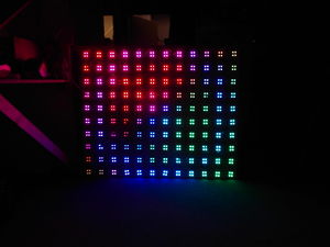
The Led wall continues its life as our Fireplace
Project to LED'ify the outside facing glass 'block' wall. each glass box will be a pixel the space
The device
the Led-wall is currently housed in a surround that makes it look more like a proper fire-place; made of MDF , created by User:milo user:justa user:einstein for use on the UrbanResort open day of 20130921.
It's been fited with a set of switches on the left hand side that operate the functions of the led-wall and/or a power-bar mounted inside the left-most column of the fireplace.
The power-bar is supplied so that you can turn on any lamps or other 'peripherals' belonging to the fireplace with one simple action.
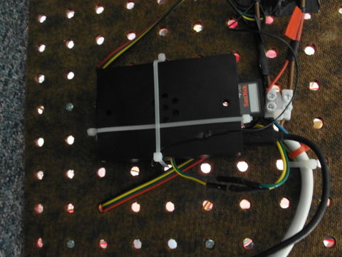
When turning on the fireplace, please allow one minute for the RaspPI to boot. It loads the firmware from an SD card and is not 'insta-on'
it will automatically start doing the fire. to run the all the animations
sudo bash ; cd /home/erik/lewd/src ; python ledshow.py -spi
Doesn't work!
- log in to ledwall using the user techinc (pw is same as the wifi)
-
git checkout https://github.com/techinc/lewd.git -
for the C fireplace: cd c ; ./fire /dev/spidev0.0 (should be started automatically by /etc/rc.local) -
for the python implementation: cd src ; python ledshow.py -spi
Hardware
Design
Overview
 Raspberry Pi ===(SPI)===> ledwall
       ^                       ^
       | (5V)                  | (12V)
       \----------PSU ---------/
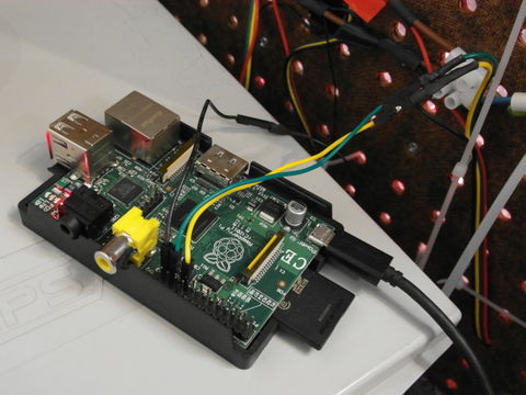
Raspi GPIO pin-out
The code uses the hardware SPI present on the the Raspberry Pi.
- Green wire on Pin 23 is Clock (SCLK)
- Yellow wire on Pin 19 is Data (MOSI)
- Black wire
should be connected to a ground pin.does not have to be connected to the ground pin, not having a common ground works as well, and doesn't generate noise. - Red wire should NOT be connected to the Raspi as it will break it!
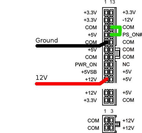
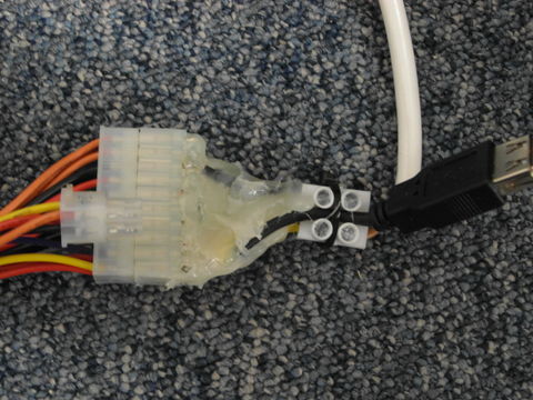
PSU
There I fixed it X-/
Software
Software Implementations
[https://github.com/techinc/lewd The current python based implementation called lewd] runs on the machine connected to the LED-Wall over a serial port.
The older javascript node.js version can communicate with the python implementation to push frames to the LED-Wall using TCP sockets.
Python documentation (temporary location) http://old.villavu.com/merlijn/lewd
Lewd
The Python (lewd) implementation features several backends. -serial, -spi, -net and -local (which renders on an SDL screen).
See the file "ledwall.py" for an example on how to use all these different LedWall frontends. At the space, you should typically use RemoteLedScreen to interface with the (already running) server to the LEDWall.
To just play around with the code locally, look into the VirtualLedScreen code; you will need to install pygame to actually use the local UI.
Python documentation (temporary location)
http://old.villavu.com/merlijn/lewd
Photos & Videos
OLD
Alternative configuration using Arduino (Obsolete)
 computer ===(serial over usb)===> arduino ===(SPI)===> ledwall
                                                           ^
                                                           | (12V)
                                                          PSU
Arduino code
#include <SPI.h>

void setup()
{
    Serial.begin(1000000);
    SPI.begin();
    SPI.setBitOrder(MSBFIRST);
    SPI.setDataMode(SPI_MODE0);
    SPI.setClockDivider(SPI_CLOCK_DIV16);
}

void loop()
{
    uint8_t c;

    for(;;)
    {
        while (!Serial.available()) {}

         /* 254 signals end of frame in the communication
          * over the serial port
          */
         if ( (c = Serial.read()) == 254 )
            delay(1); /* the WS2801 chips will latch after not getting
                       * any data for .5ms, so we wait 1ms
                       */
        else
            SPI.transfer(c); /* not end of frame? push data */
    }
}
Arduino pin-out
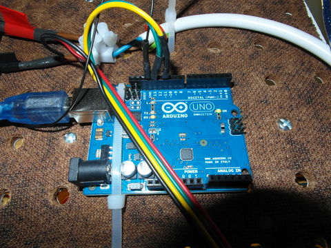
The code uses the hardware SPI present on the the ATMega
- Green wire on Pin 13 is Clock
- Yellow wire on Pin 11 is Data
- Black wire
should be connected to the arduino's ground pin.does not have to be connected to the ground pin, not having a common ground works as well, and doesn't generate noise. - Red wire should NOT be connected to the arduino as it will break it!
| Is on Fire? | Definitely |
|---|
